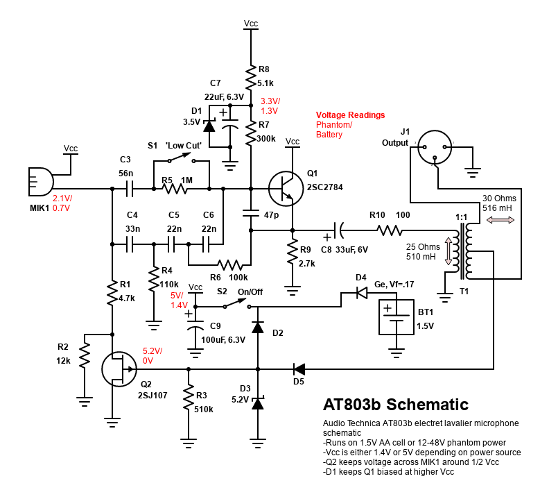
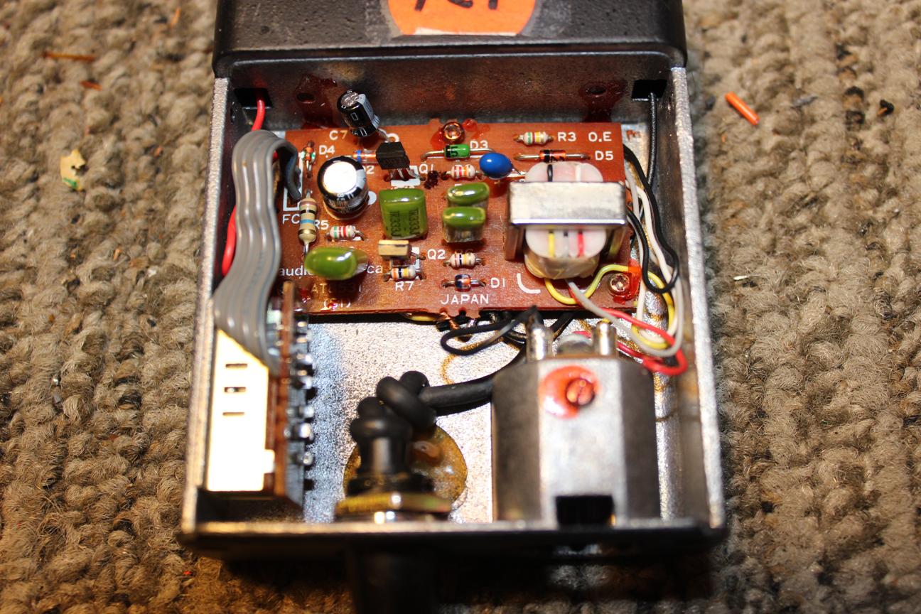
 After a bit of poking around, this is the schematic that I ended up with. I took voltage measurements at several spots for both battery and phantom power which are shown in red.
The microphone is powered by the voltage from Vcc to R1 and sends a signal to coupling caps C3 and C4. The low cut control switches in a high value resistor to force the signal through a series of high pass filters formed by C4, R4, C5, R6, and C6. The signal then enters the base of Q1 and appears across R9, buffered and ready to drive T1 through coupling cap C8 and R10. Two outputs are taken from the transformer secondary, each with 1/2 the amplitude of the primary and opposite the other in phase. This balanced signal pair is connected to pins 2 and 3 of the XLR output jack.
When powered by a battery, germanium diode D4 protects the circuit and the battery from reverse polarity. Using a germainum diode eliminates the large voltage drop that would ammount to almost half of the available supply voltage if a silicon diode were used.
Phantom power is applied to the hot and cold pins of the XLR jack. A small DC current flows from both ends of the secondary through center tap and then through D5. D3 regulates the voltage on the other side of D5 and D2 supplies the Vcc node. When this voltage is present, D4 is reverse biased, cutting off the battery supply. D2 also keeps the battery voltage from turning off Q2 when phantom voltage is not used. Since Q2 is a depletion mode JFET, it has a low resistance between its drain and source until voltage is present at its gate. It acts as a short during battery operation and as a large resistance with phantom power (12k max across Q2 because of R2). This keeps the voltage across the microphone from geting too high. Zener diode D1 serves a similar voltage limiting function, ensuring that Q1 does not reach saturation when operating on phantom power.


