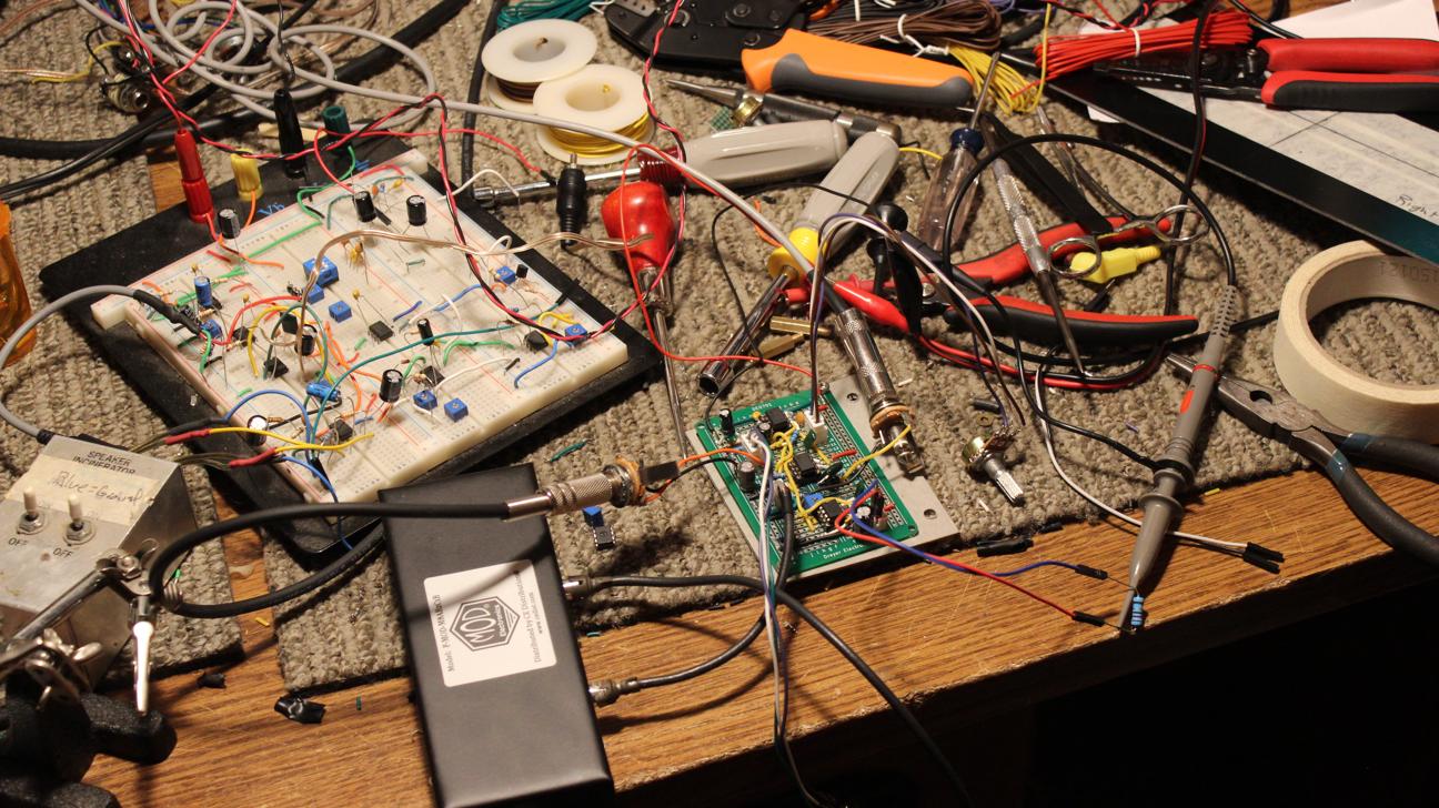
 The breadboard on the left is where I started. Once I was happy with that, I copied the circuit onto the protoboard.
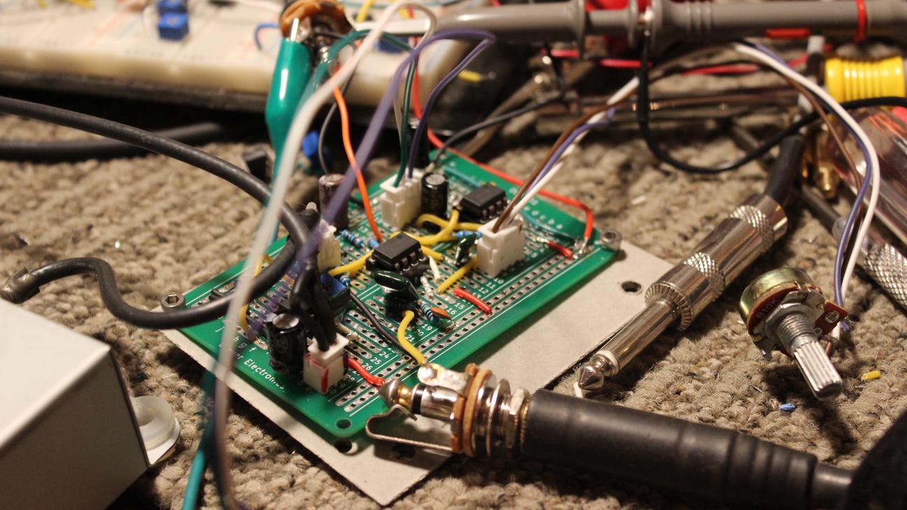 It's always a pain to crimp a bunch of connectors but I was glad I did when I started making changes to the design. I used JST-XH connectors for everything on the main board and mounted it to a piece of fiberboard.
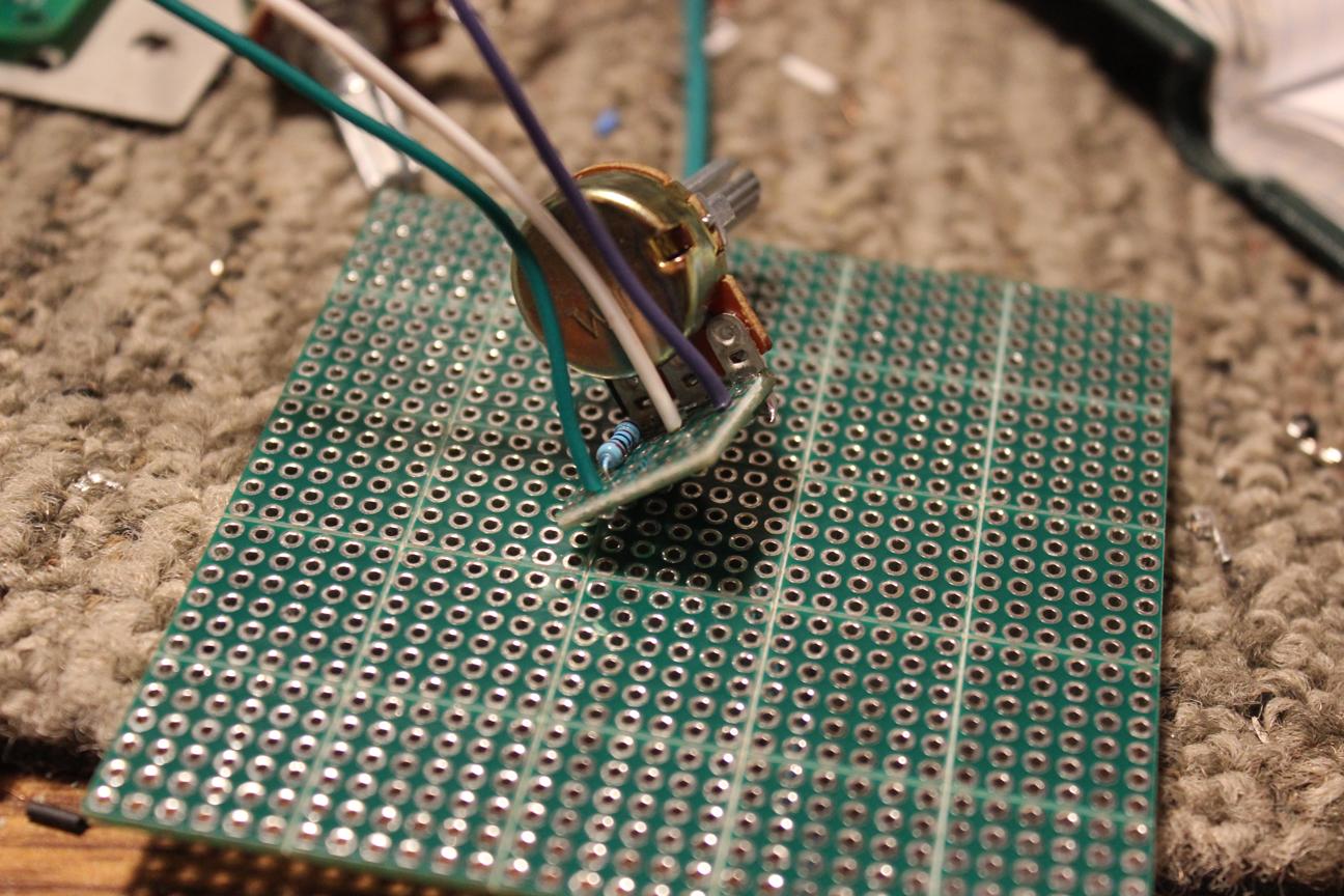 I use these
snappable PCB's
for making connections to through hole pots and for adding related components like the gain-limiting resistor in this picture. Shoutout to
Dryer Electronics
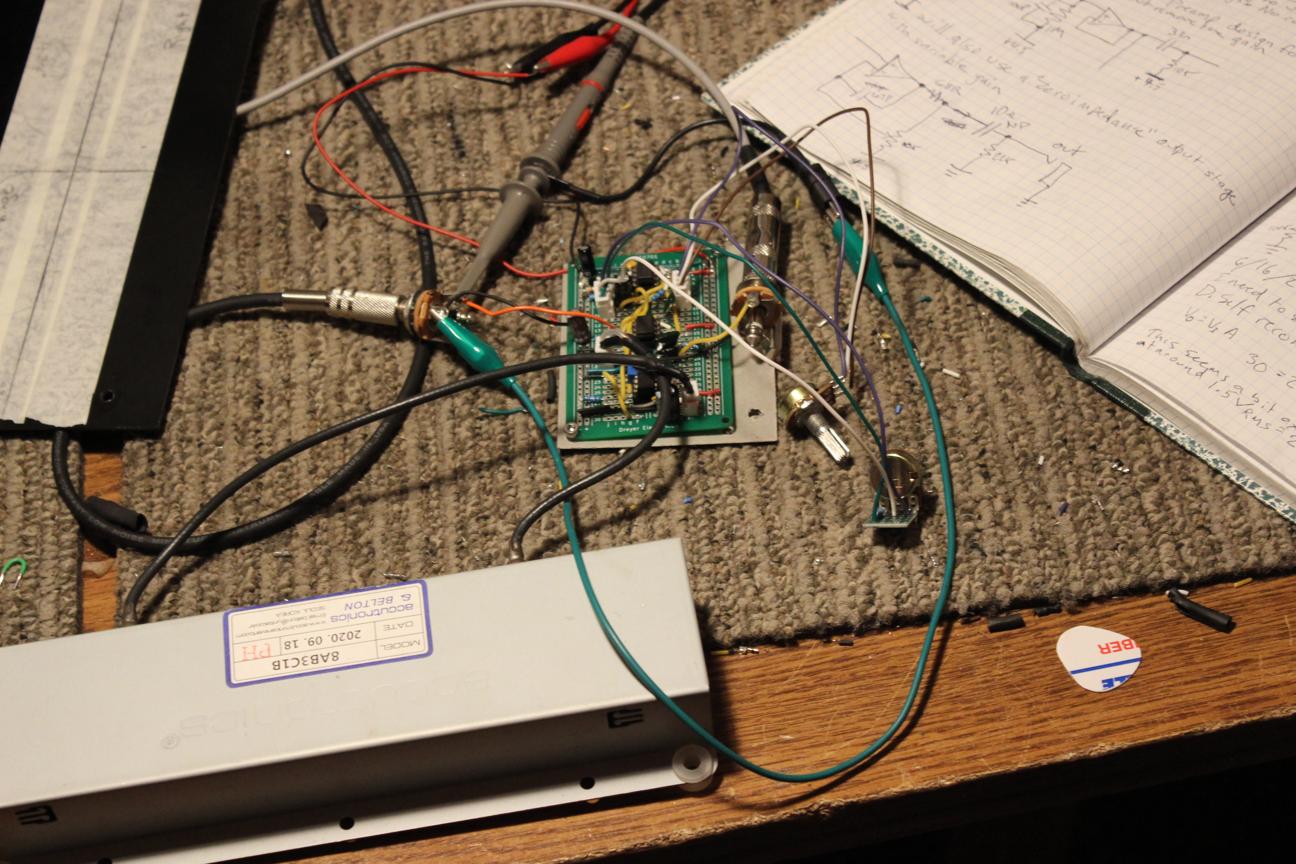 Cleaned the bench for a final test after making some changes to the circuit and it's ready to assemble.
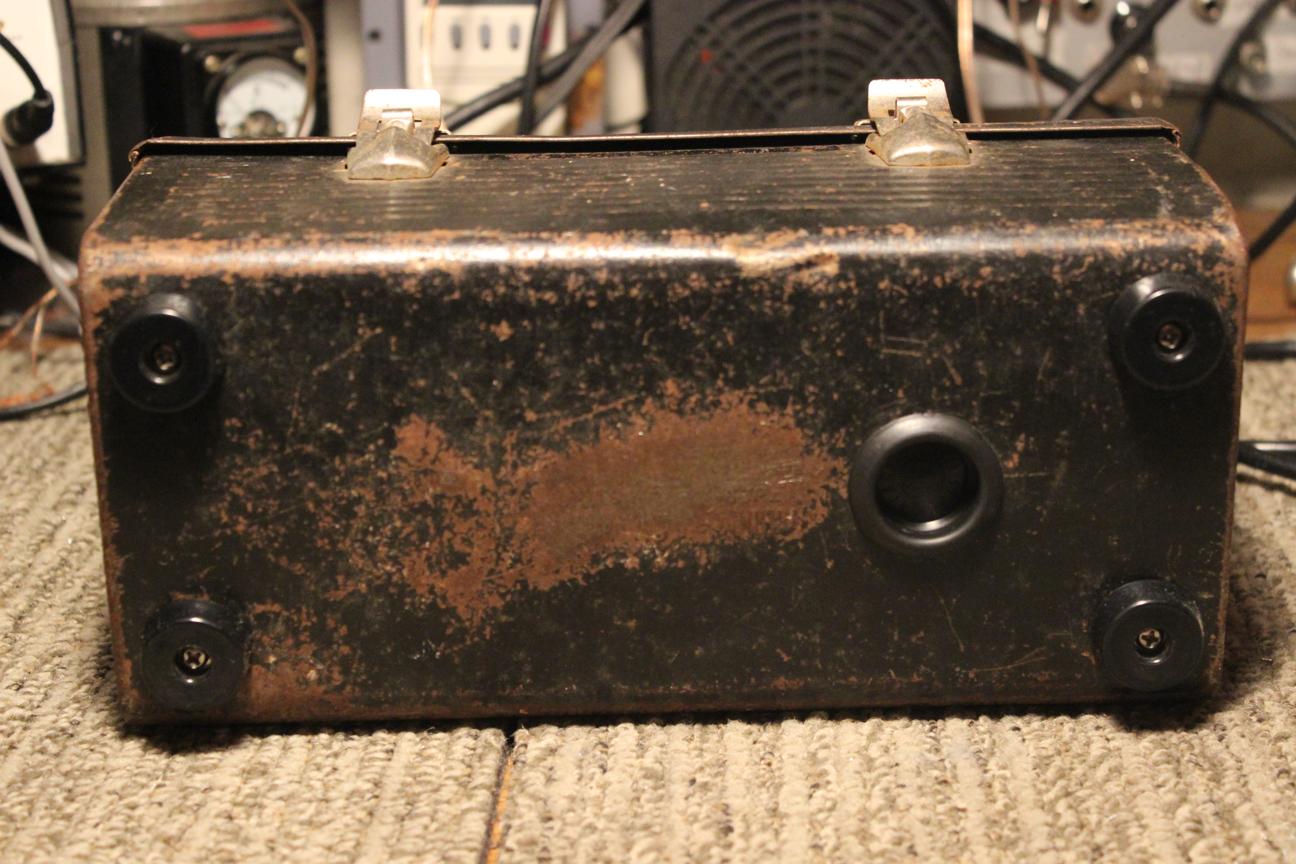 I couldn't believe how perfectly a type 8 reverb tank fits inside a lunchbox like this. The stamped feet of the lunchbox match almost exactly with the mounting holes of the tank. I added some rubber feet and used extra long machine screws to extend through the tank grommets. The plastic plug allows for access to the springs so I could stuff the tank with foam before shipping it.
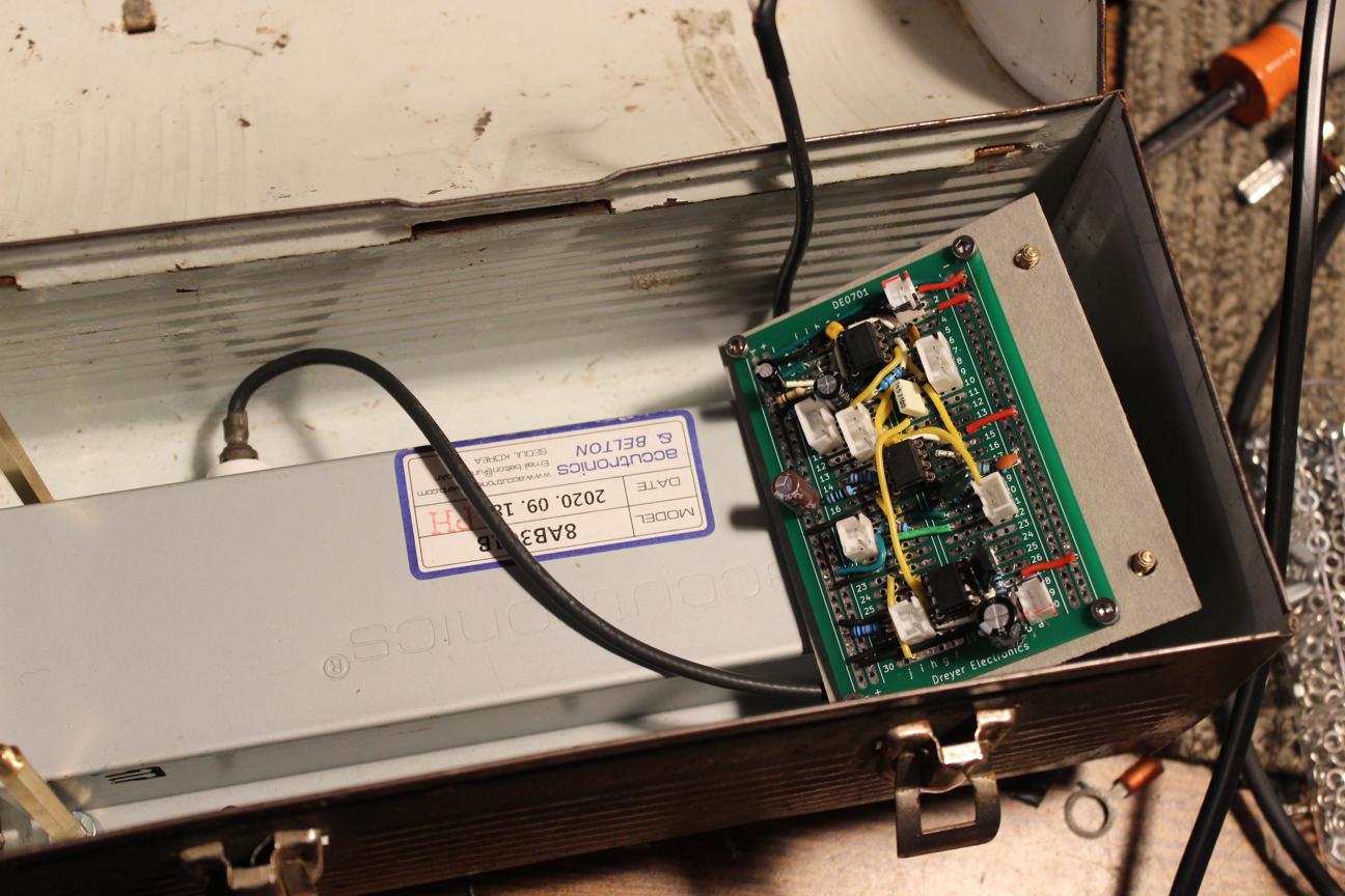 Inside the lunchbox, I used M4 standoffs connected to the foot screws.
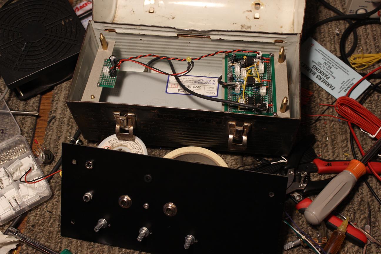 Four more standoffs secure all the electronics. The power supply board is mounted on another fiberboard strip to the left and the control panel has been drilled and controls test-fitted in front.
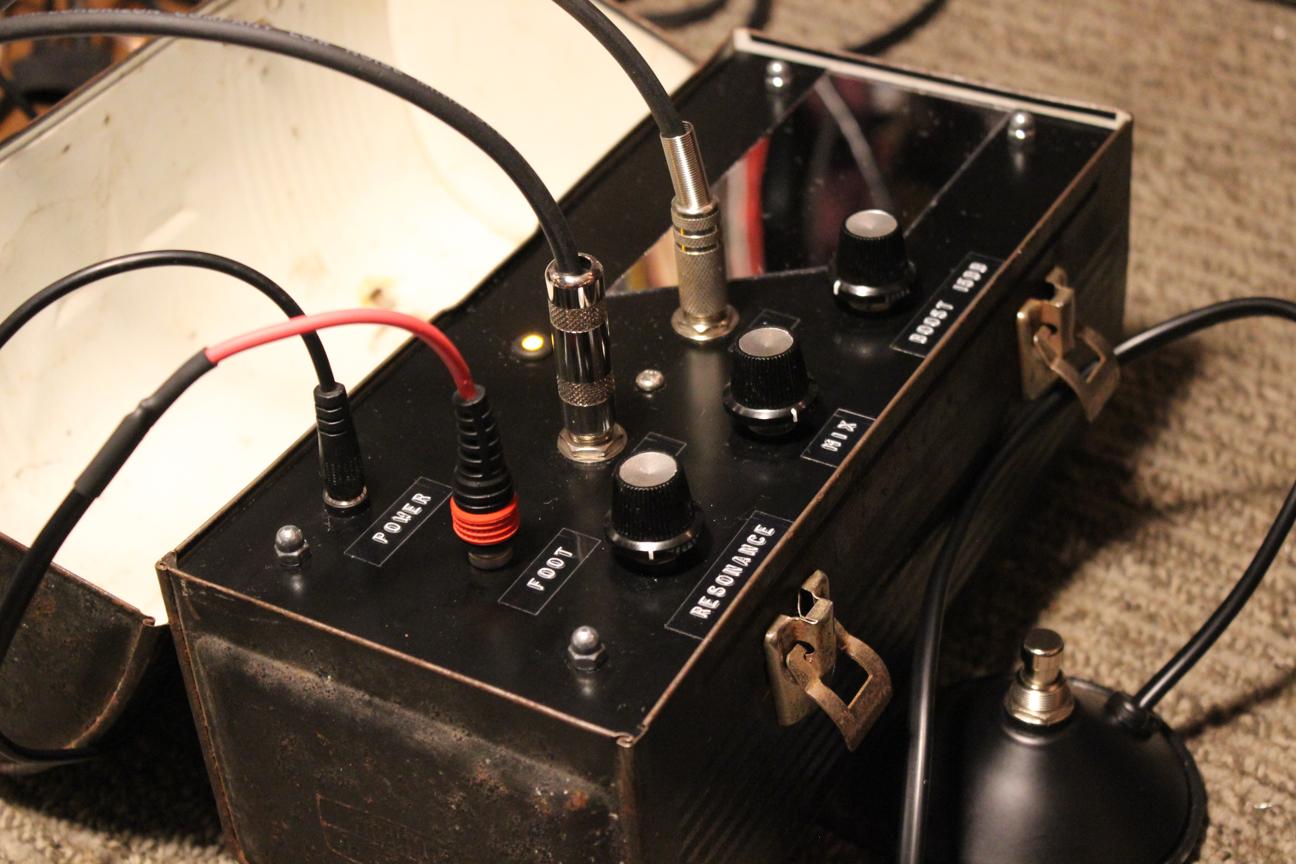
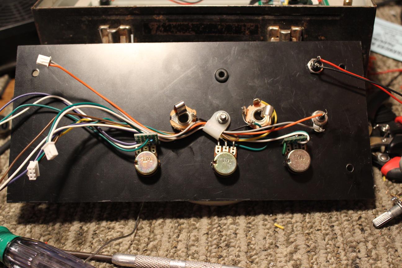 Keeping the wires tidy. I ended up installing shielded cable on the input jack just because it felt a little wrong not to but I actually didn't have problems with noise either way.
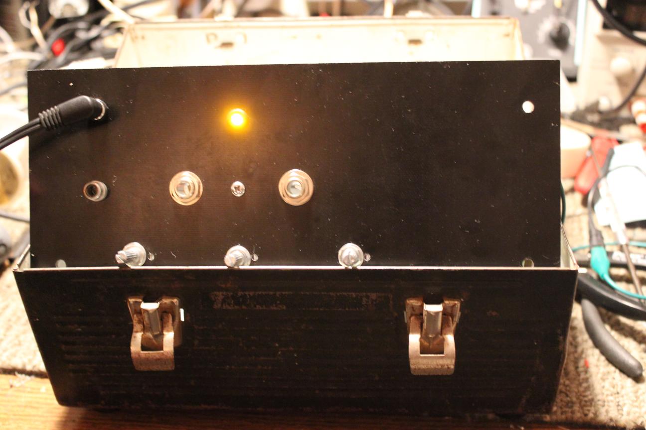 It lives
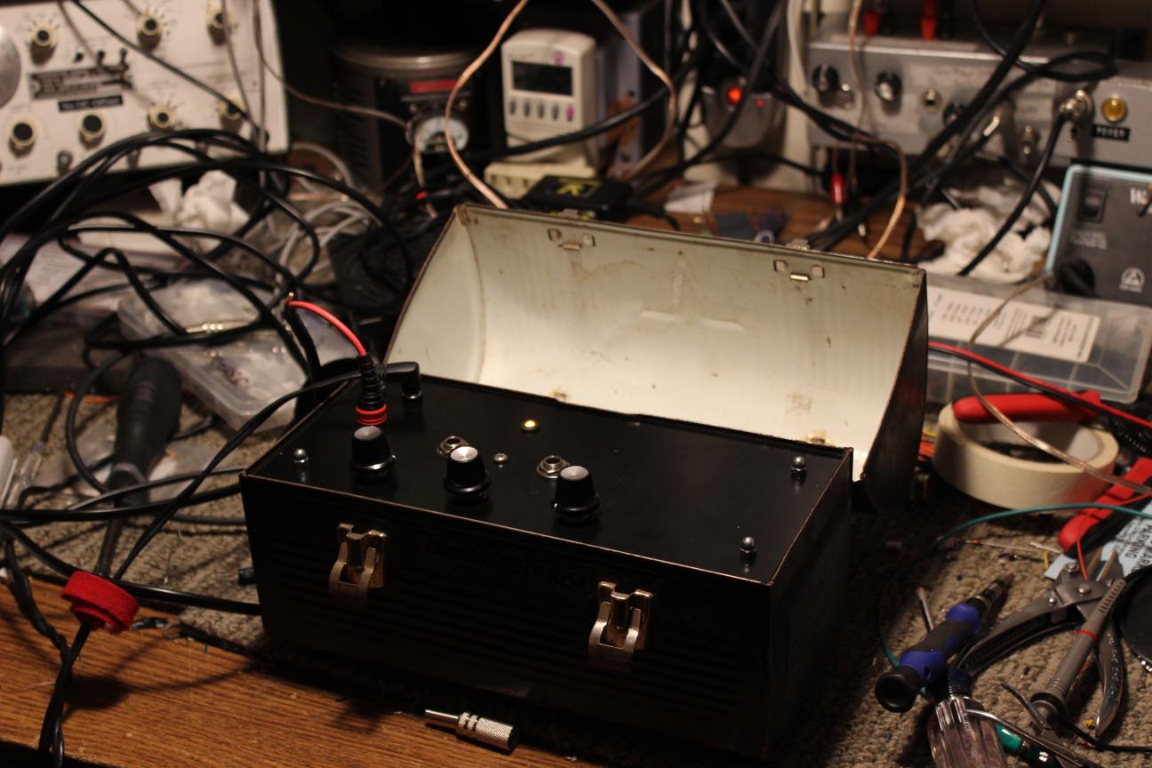 First tests
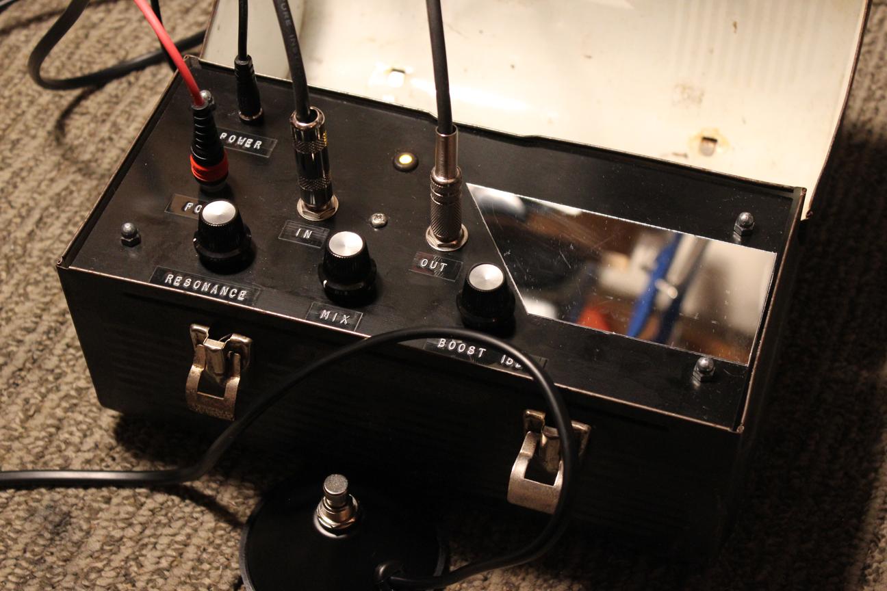
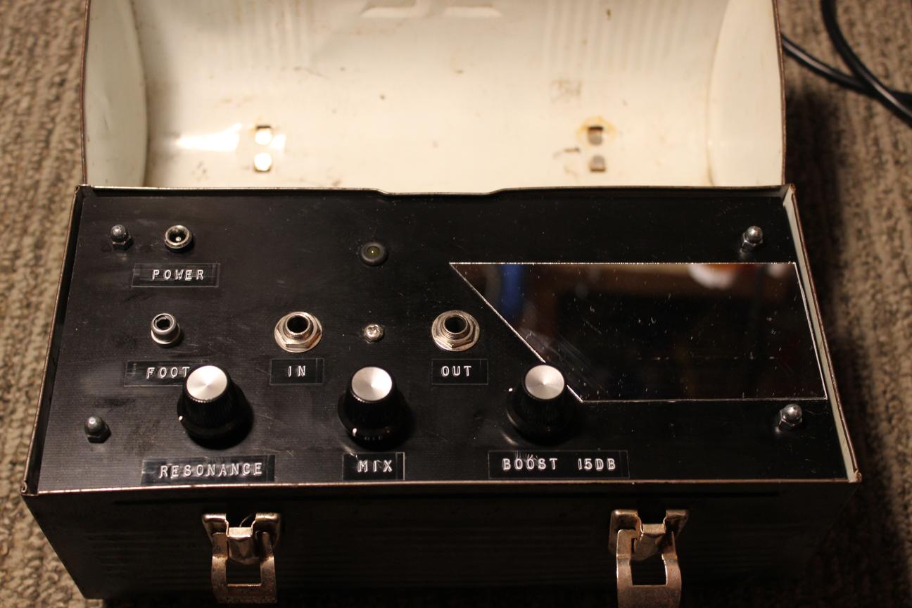 The control panel looked kind of boring so I added an adhesive plastic mirror cut to the same angle as the controls. Mirrors look cool onstage. I also labeled all the controls and tightened the acorn nuts for the final assembly.
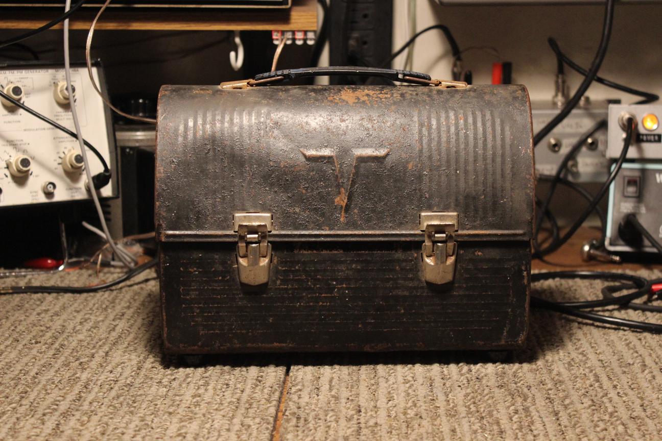 From the outside you'd never know.
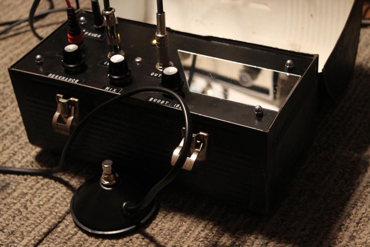 Very stoked with how this one turned out
 Once I had tested the reverb out for a while to make sure it was working as intended, I copied the final schematic into EAGLE. Below is the circuit that was on the proto-board.
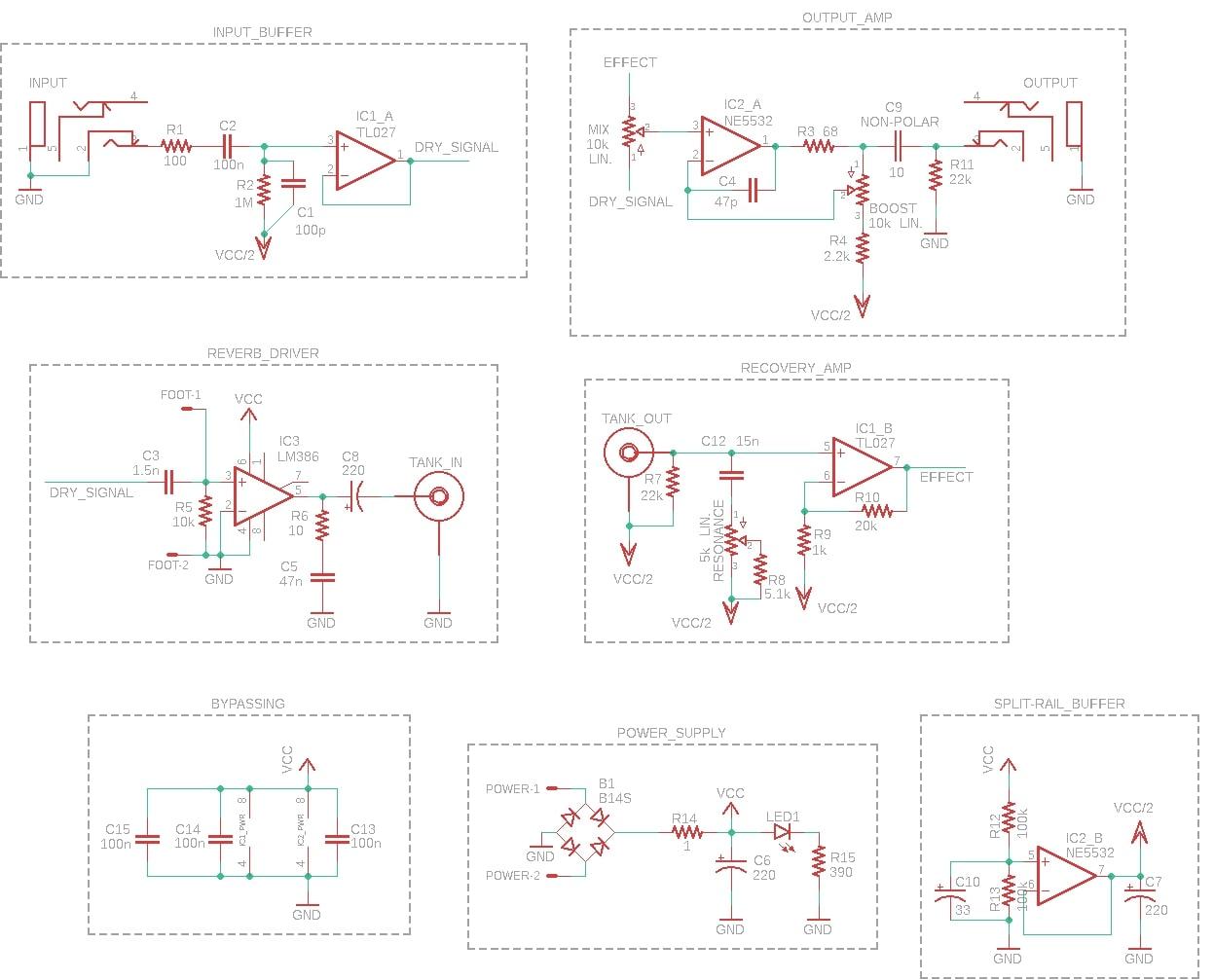
The input and output amplifiers are based on circuits from D. Self, Small Signal Audio Design . The input is a simple guitar input buffer and the output is a "zero impedance" amplifier with 15dB of gain available through the pot. The wet and dry signals are mixed in the 10k potentiometer at the non-inverting input of the output amplifier.
The reverb driver is an LM386 audio amplifier configured for 20dB of gain. My reasoning for using this part was based on its cost, parts count, and intended purpose of driving audio through 8 ohm loads at low power. I have yet to actually crunch the numbers but it seems like a pretty good use for this chip. I want to go more in depth about that in the future and compare different tank drivers.
At the non-inverting input, C3 and R5 form a high pass filter which attenuates the signal across the whole guitar spectrum and leaves the signal with a 6dB/octave slope that helps to flatten the low-pass characteristics of the tank's input transducer. C3 was chosen to give 28mA through the 8Ω coil after 20dB of gain from the LM386 with a signal voltage of 100mV at the input.
The recovery amp uses the other side of the TL072 and has a gain of 20. The "resonance" control resistively couples C12 across the output transducer coil, forming a tank circuit with a frequency in the treble range. I picked C12 by ear to give the most pleasing attack sound with a guitar. R8 is there to approximate a log taper and give a more useful range to the pot.
The power supply uses a full bridge so that any polarity supply can be connected. In the future, it might be a good idea to add some regulation and another filter stage to ensure that AC supplies won't cause any trouble but for now, the circuit works with voltages up to 15V DC.

