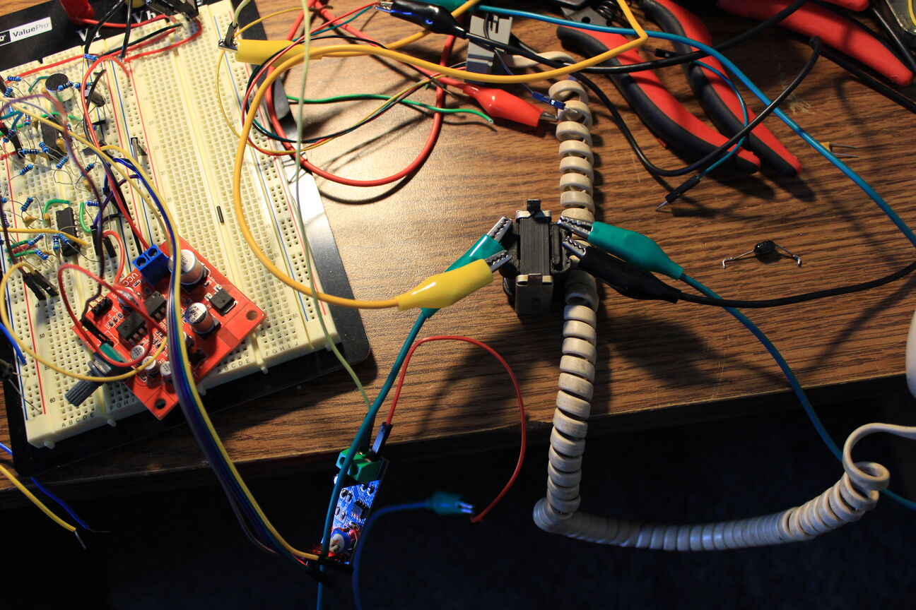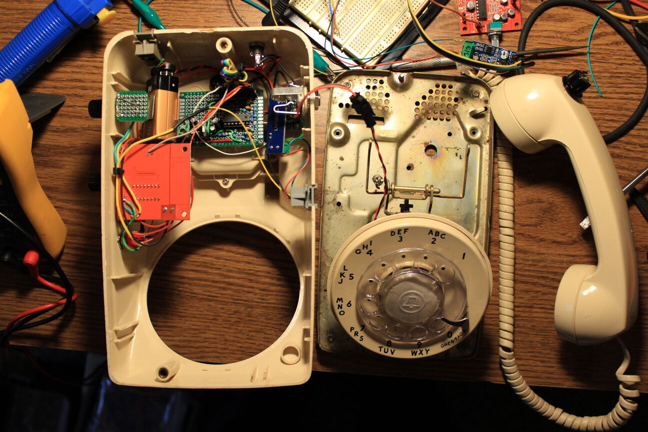

This is the first bandpass filter I put together on the breadboard. It's a 6 pole Chebyshev which ended up getting scrapped. Next to it is the Western Electric model 500 chassis that needs to be gutted.

When connecting an electret mic to the filter, I heard a resonance that was very un-musical. Ringing is to be expected with this type of filter though and is traded off for the super sharp cutoff that the Chebyshev has. I didn't expect it to be that noticeable though. A Butterworth filter is a better choice for audio so that's what I built next.

Here's a shot of the 4-pole Butterworth bandpass. It has a center frequency of 1.85kHz and a bandwidth of 3kHz. I tested it again with the mic and a signal generator and didn't hear or see any resonance so I moved on to the delay module.

I'm using this super convenient PT2399 board from Amazon. It's powered from the 9V supply and connected to the output of the filter. The pot connected to the board is for feedback level. The delay time is set with a fixed resistor.

To make delay time adjustable, R27 must be removed and a 20 kΩ pot needs to be added.

After testing the output from the delay module, I began working on the handset monitor. I used another convenient Amazon PCB this time to drive the speaker. Its an LM386 module with adjustable gain. I tried an output transformer between the speaker and the LM386 but the high impedance speaker didn't need it and it made no difference in output volume.

This is the electret board that I made to go in the handset. It is possible to use the carbon capsule that comes in the handset but it's a little noisy, distorts more, and requires a trans-resistive amplifier. For this mic, I wanted to have a less distorted sound so I went with an electret.

mounted in the handset.

At this point, I added the volume control for the monitor, removed the diode clamp from the speaker, and rewired the handset for +5V, ground, monitor signal, and mic signal.

Here's the diode clamp from the handset. I think it's there to ensure that the phone doesn't get too loud and hurt your ears. I want as much volume as I can get from this though so I removed it. It can be used it to clip an amplified signal as a cheap distortion effect or limiter so I'm throwing it in the parts bin for later.

I wired the handset up for a final test and then started soldering the board.

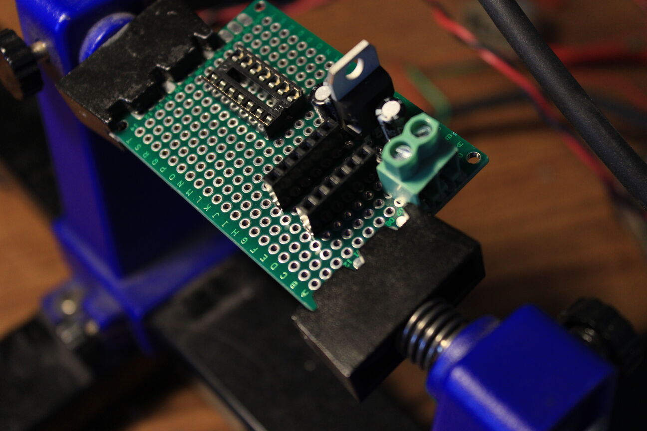
sockets, regulator, and filter caps

added more filter caps, a split rail buffer for virtual ground, and the first stage of the filter

second stage added and tested

I crimped a connector to make it easier to remove from the final assembly when it doesn't work.

Starting to mount parts in the case. I installed a switch for the filter, a DC barrel jack, some LED's, and a board for the time control pot.

Drilled a couple holes and used epoxy to mount the standoffs

Using a 1/4" TRS jack to act as a power switch so the battery doesn't drain unless its plugged in

battery clip glued in place

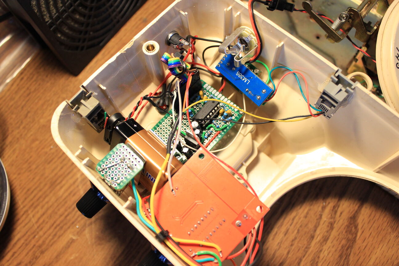
I soldered a socket to another tiny proto-board to act as a mount for the LM386 module.

Final testing of the rats nest. Of course it didn't work on the first try.

Using the breadboard as a guide, I traced the problem to a wrong connection on the filter board.

Once it worked, I cleaned up the wiring job with some zip ties.

I wanted the act of hanging up the phone to mute its output so I connected a normally open section of the line switch across the output. Now it grounds the output when you hang up the phone.

another angle

ready for some final audio tests

All put together. My friend 3D printed some mic clips that fit the handset perfectly

 This is the first bandpass filter I put together on the breadboard. It's a 6 pole Chebyshev which ended up getting scrapped. Next to it is the Western Electric model 500 chassis that needs to be gutted.
 When connecting an electret mic to the filter, I heard a resonance that was very un-musical. Ringing is to be expected with this type of filter though and is traded off for the super sharp cutoff that the Chebyshev has. I didn't expect it to be that noticeable though. A Butterworth filter is a better choice for audio so that's what I built next.
 Here's a shot of the 4-pole Butterworth bandpass. It has a center frequency of 1.85kHz and a bandwidth of 3kHz. I tested it again with the mic and a signal generator and didn't hear or see any resonance so I moved on to the delay module.
 I'm using this super convenient PT2399 board from Amazon. It's powered from the 9V supply and connected to the output of the filter. The pot connected to the board is for feedback level. The delay time is set with a fixed resistor.
 To make delay time adjustable, R27 must be removed and a 20 kΩ pot needs to be added.
 After testing the output from the delay module, I began working on the handset monitor. I used another convenient Amazon PCB this time to drive the speaker. Its an LM386 module with adjustable gain. I tried an output transformer between the speaker and the LM386 but the high impedance speaker didn't need it and it made no difference in output volume.
 This is the electret board that I made to go in the handset. It is possible to use the carbon capsule that comes in the handset but it's a little noisy, distorts more, and requires a trans-resistive amplifier. For this mic, I wanted to have a less distorted sound so I went with an electret.
 mounted in the handset.
 At this point, I added the volume control for the monitor, removed the diode clamp from the speaker, and rewired the handset for +5V, ground, monitor signal, and mic signal.
 Here's the diode clamp from the handset. I think it's there to ensure that the phone doesn't get too loud and hurt your ears. I want as much volume as I can get from this though so I removed it. It can be used it to clip an amplified signal as a cheap distortion effect or limiter so I'm throwing it in the parts bin for later.
 I wired the handset up for a final test and then started soldering the board.
 sockets, regulator, and filter caps
 added more filter caps, a split rail buffer for virtual ground, and the first stage of the filter
 second stage added and tested
 I crimped a connector to make it easier to remove from the final assembly when it doesn't work.
 Starting to mount parts in the case. I installed a switch for the filter, a DC barrel jack, some LED's, and a board for the time control pot.
 Drilled a couple holes and used epoxy to mount the standoffs
 Using a 1/4" TRS jack to act as a power switch so the battery doesn't drain unless its plugged in
 battery clip glued in place
 I soldered a socket to another tiny proto-board to act as a mount for the LM386 module.
 Final testing of the rats nest. Of course it didn't work on the first try.
 Using the breadboard as a guide, I traced the problem to a wrong connection on the filter board.
 Once it worked, I cleaned up the wiring job with some zip ties.
 I wanted the act of hanging up the phone to mute its output so I connected a normally open section of the line switch across the output. Now it grounds the output when you hang up the phone.
 another angle
 ready for some final audio tests
 All put together. My friend 3D printed some mic clips that fit the handset perfectly
