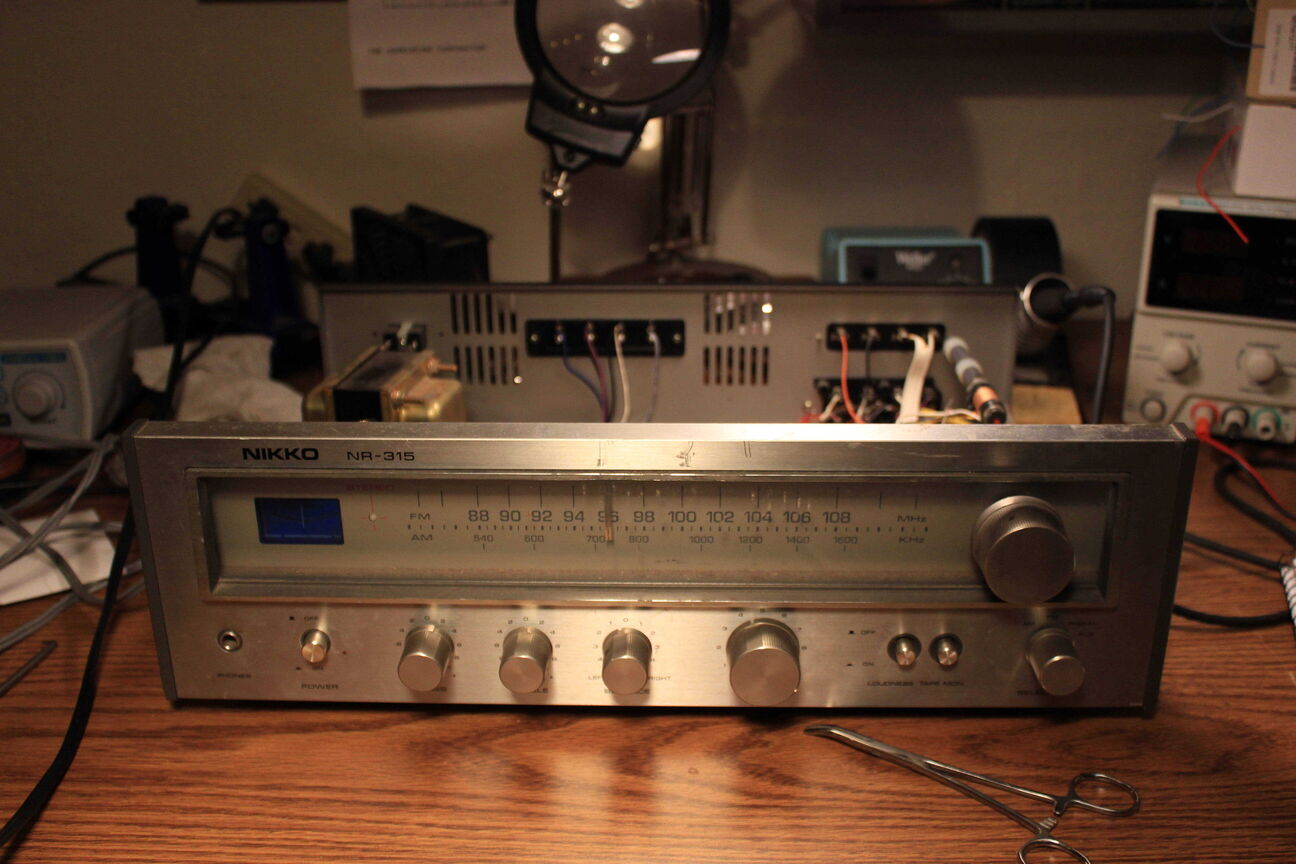
The first thing I noticed was that all but one of the display bulbs had burned out.
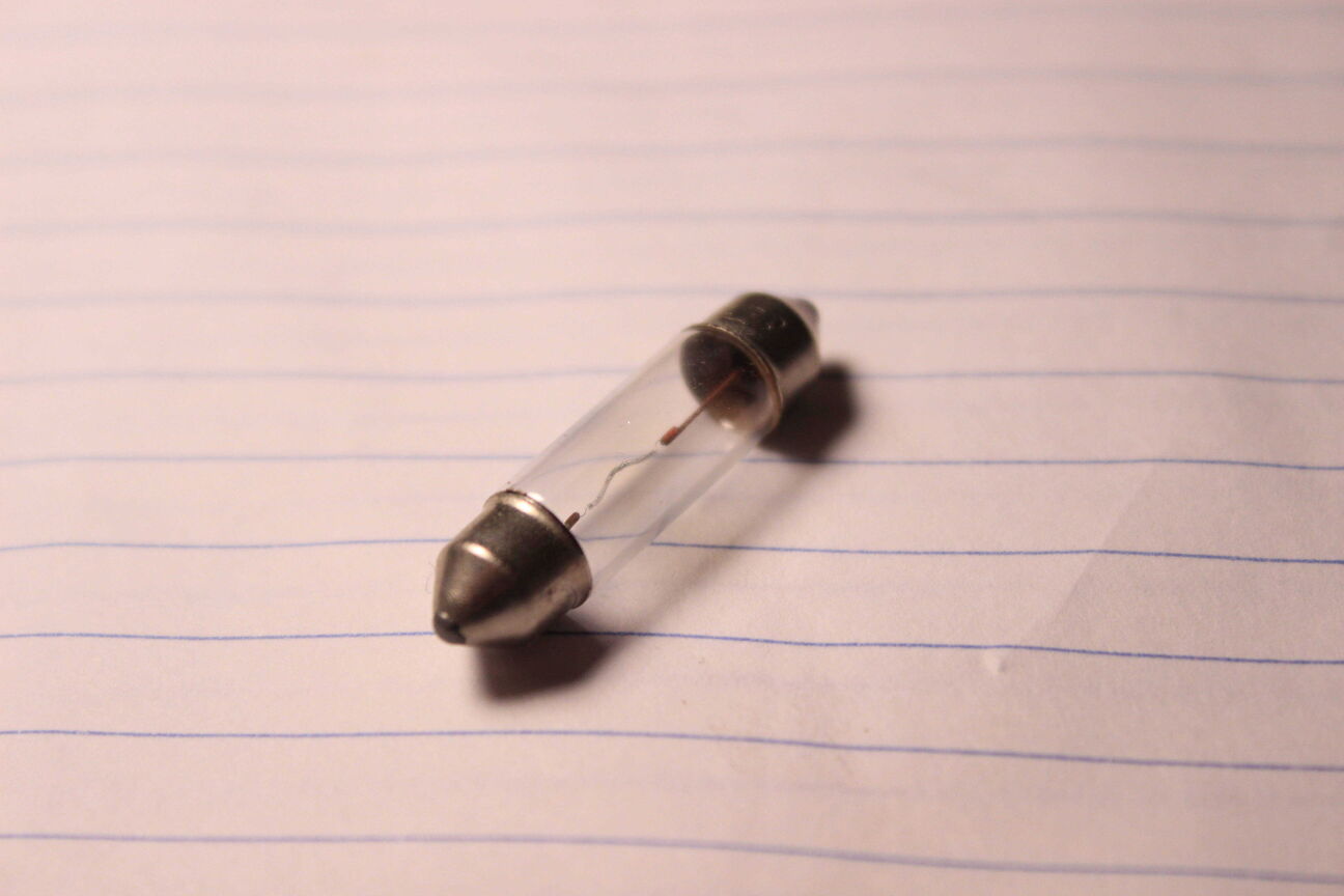
The display used these fuse lamps that run off of 8V AC directly from a transformer tap. They each draw 300mA and they're wired in parallel through a 2A fuse.
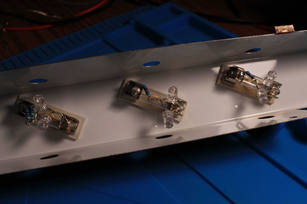
Since buying new incandescent lamps would be pricey, I decided to wire two LED's in parallel with their polarities reversed and connect them in series with a current limiting resistor to the 8V AC. I chose a 220 ohm resistor which at 4 volts gives just under 20mA. I soldered them directly to the bulbs and popped them back in the sockets. I also replaced the 2A fuse with a 1A because the LED's don't draw nearly as much current.
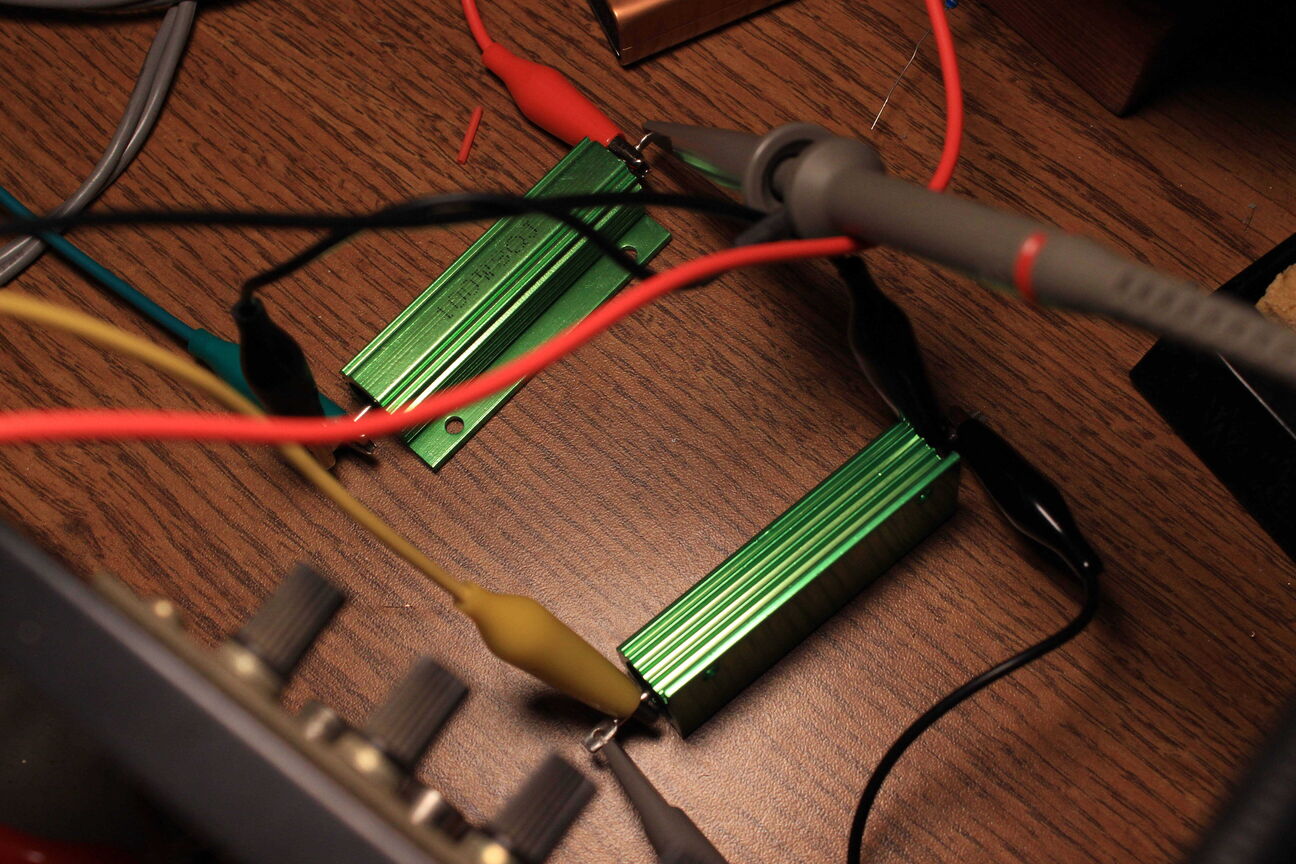
To test the amplifier circuit, I connected two 8 Ohm dummy loads to the output and sent a 1kHz sine wave through the aux input. The left channel tested fine, pushing around 11 Watts. When I moved the pan knob to the right side, however, one of the high wattage resistors began smoking so I cut the power and checked out the right channel amplifier.
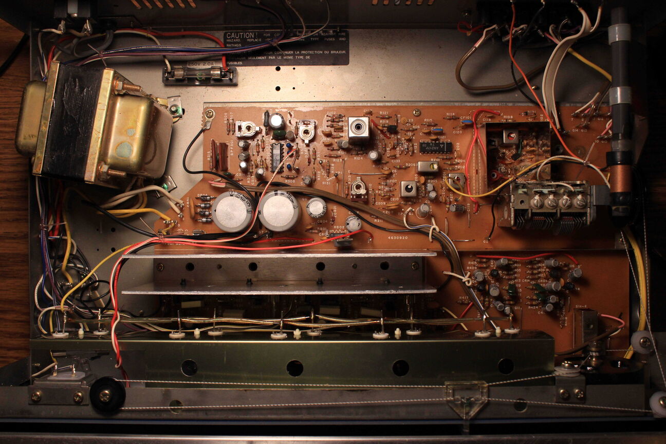
Here is a shot of the insides of the amp. I had to remove the newly replaced display lights to get to the power amplifier circuit underneath. Each channel uses two BJT's that are screwed in to the aluminum heatsink. With a visual inspection, I didn't notice anything that looked charred. I also tested the resistor that got hot and it was within spec.
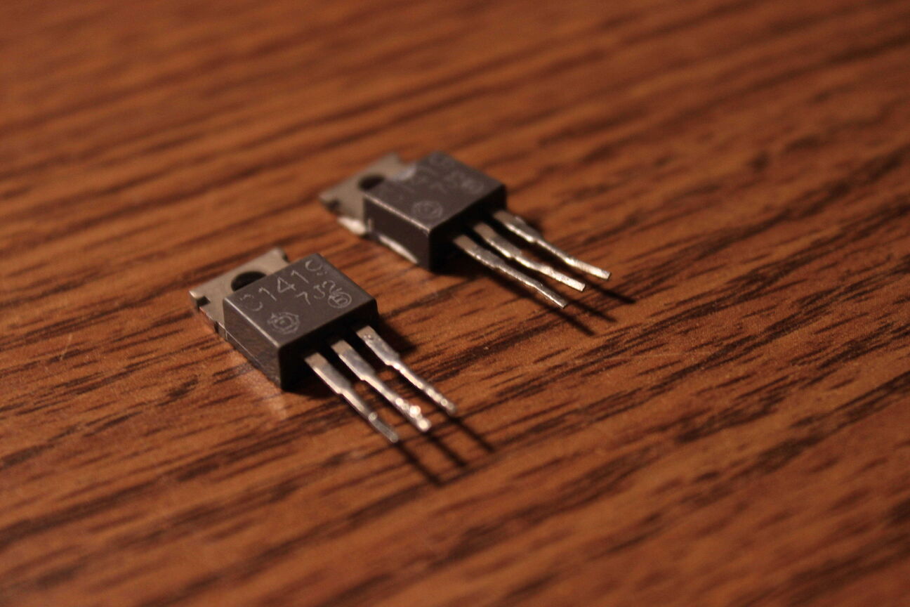
I tried testing the right channel power transistors with a component tester. One of them looked like a short from emitter to base and the other blew open. I ordered some NTE-152's to replace them. I also noticed while I was searching for a short that someone had replaced the 2A audio output fuse with a 4A on one channel and a 3A on the other. That explains why the transistors were fried.
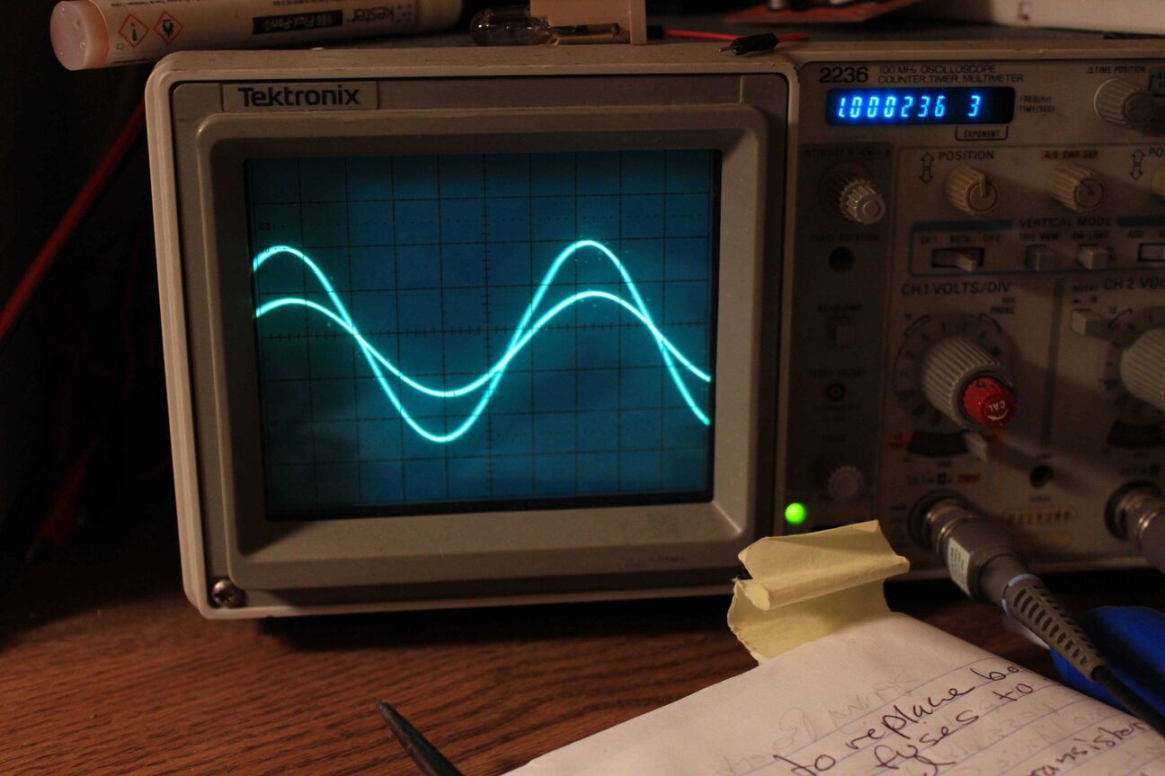
After screwing the new NTE-152's into the heatsink with some heat transfer paste and insulation, I soldered them both into the right channel and replaced the fuses with the correct values. Using the same test as before, I got good readings for both channels. Here's a shot of the scope with the pan knob turned just off center. Both channels are putting out 11 Watts now.
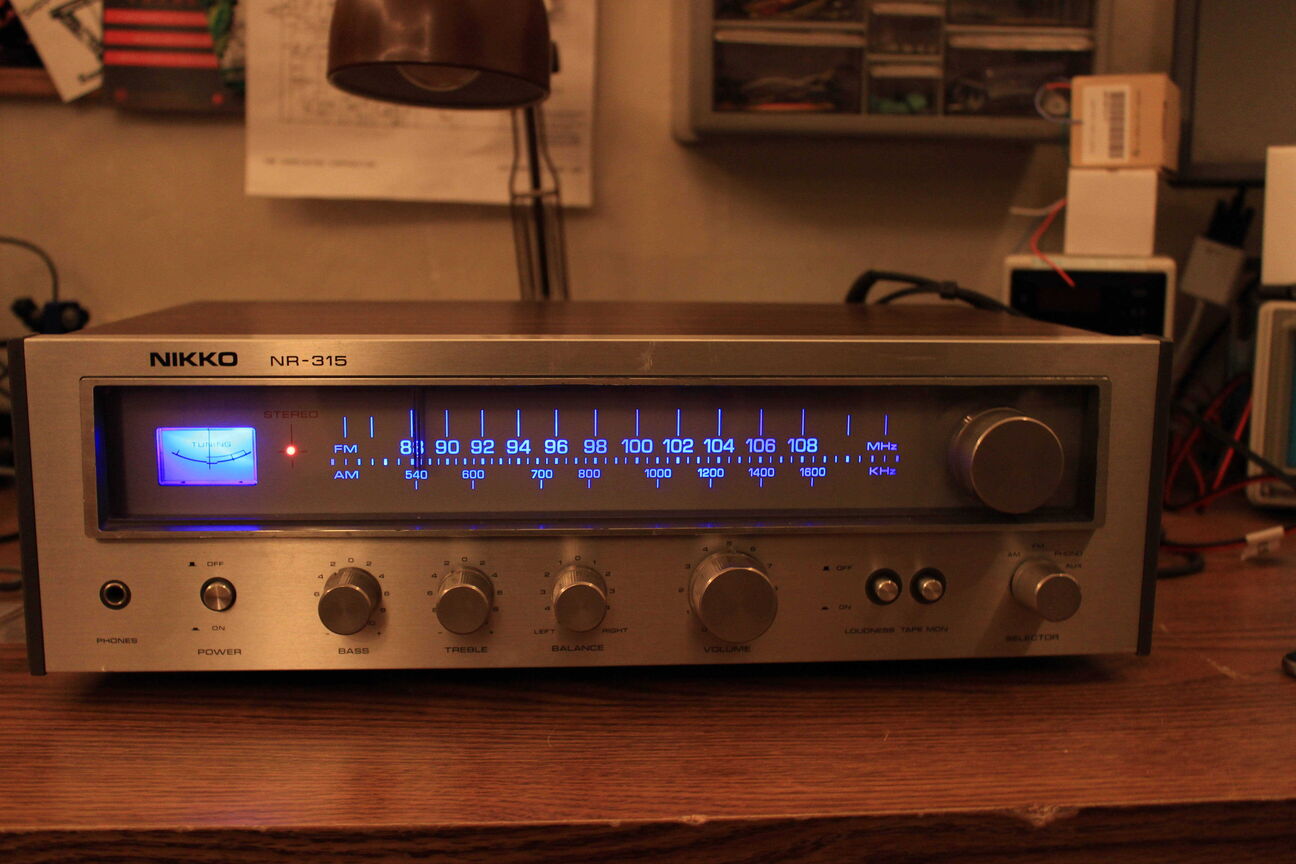
The last step was cleaning all of the switches and pots to get rid of that scratching sound that old controls have. Testing with speakers, the amp sounded good on both channels so I decided to call it on this one.
