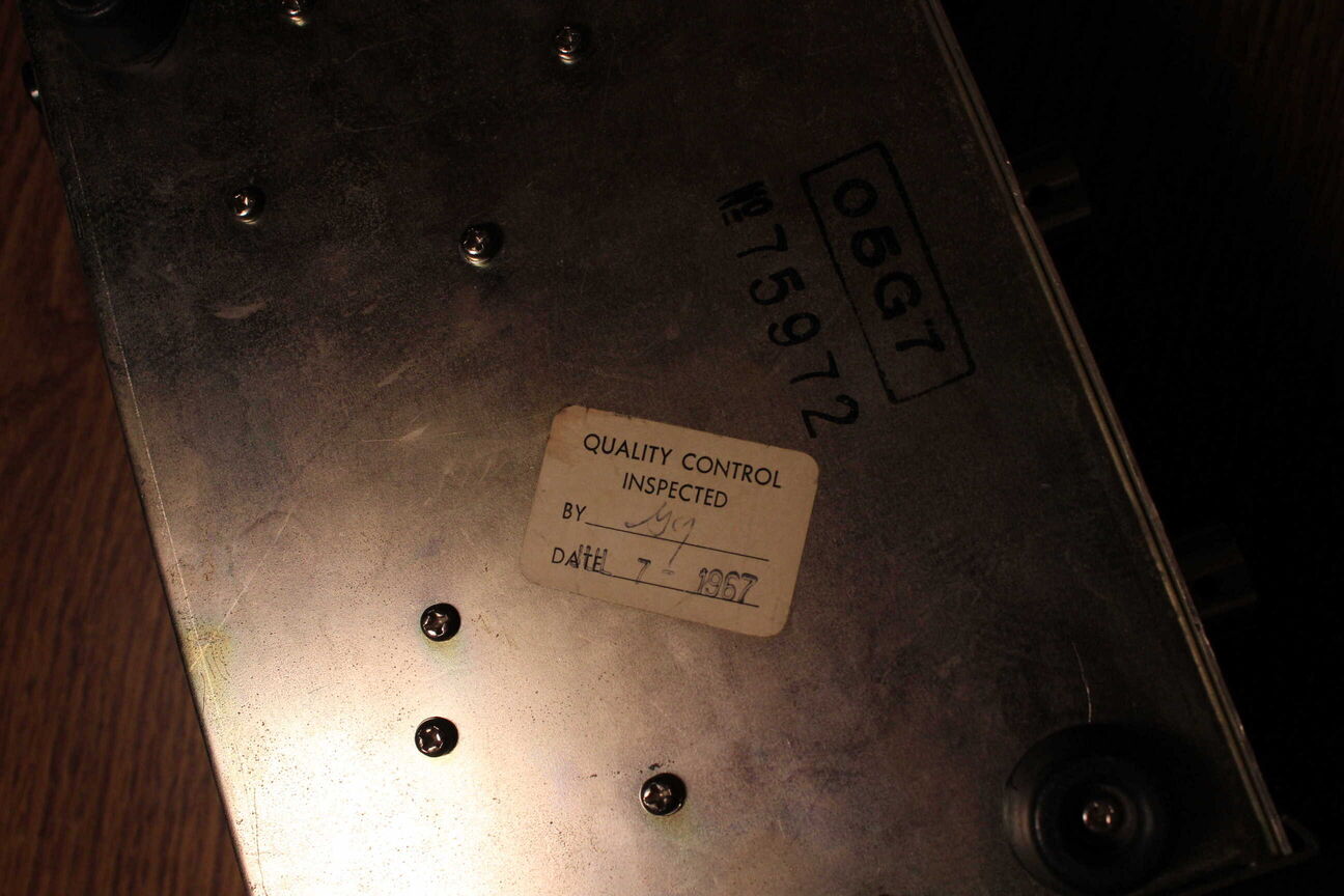
The inspection date on the bottom says this thing was made in the 60's. I'm expecting some germainium transistors.
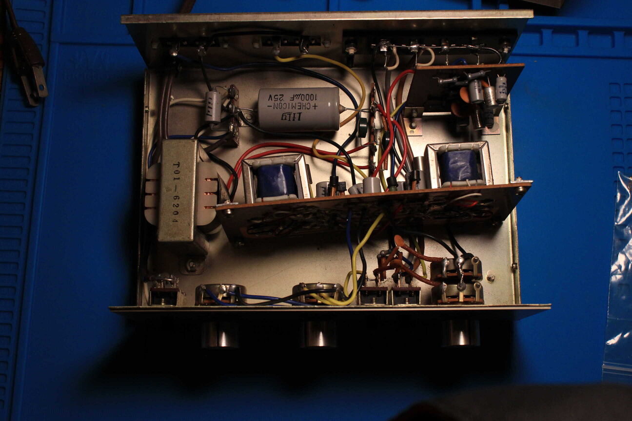
This amp is very servicable. I will definitley be changing out the filter caps in the power supply.
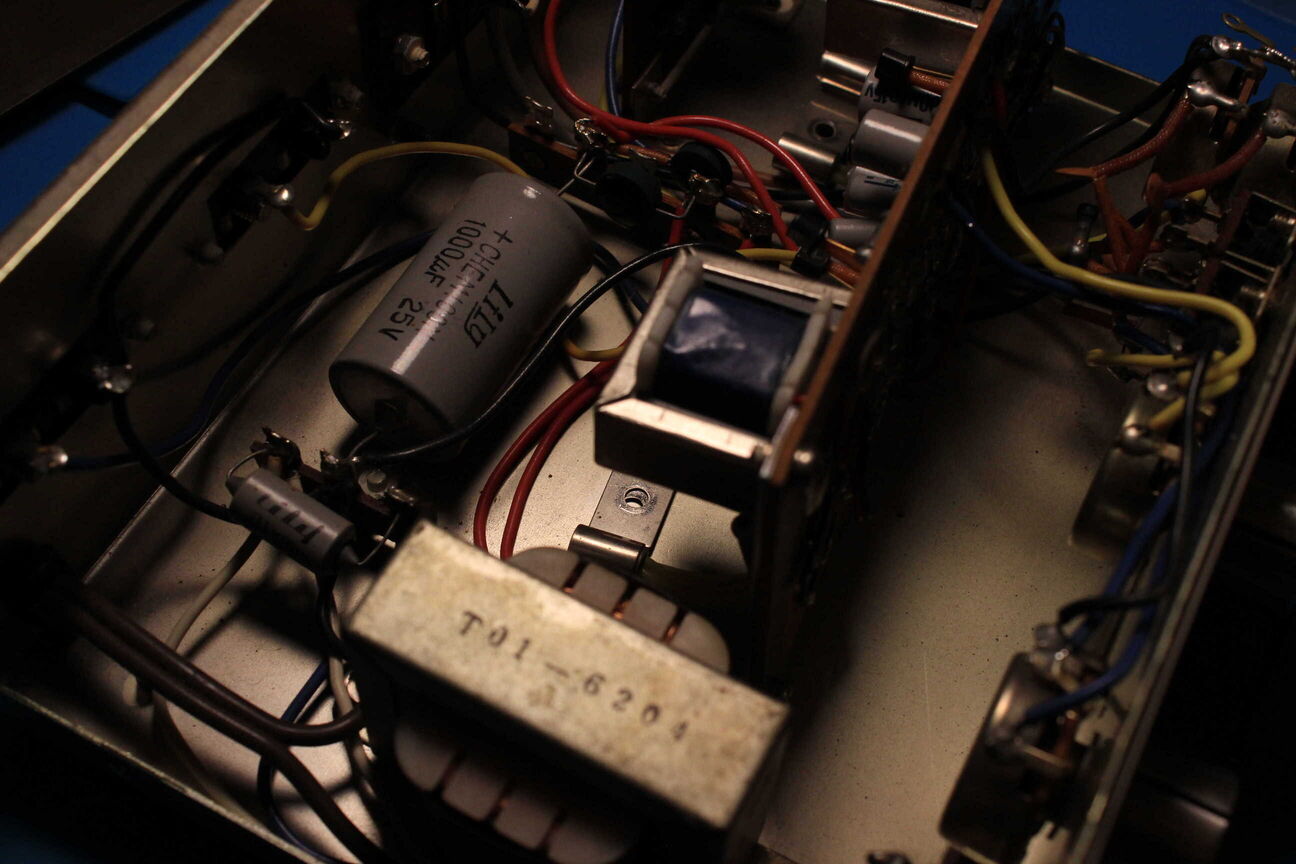
You can see the germainuim transistors that are bolted to the chasis for heat dissapation. Before doing anything, I took the values down for all the electrolytic caps in the amp and ordered replacements for the ones that I didn't have on hand. I want this amp to be reliable and there aren't that many electrolytics so I figured I'd just replace them all.
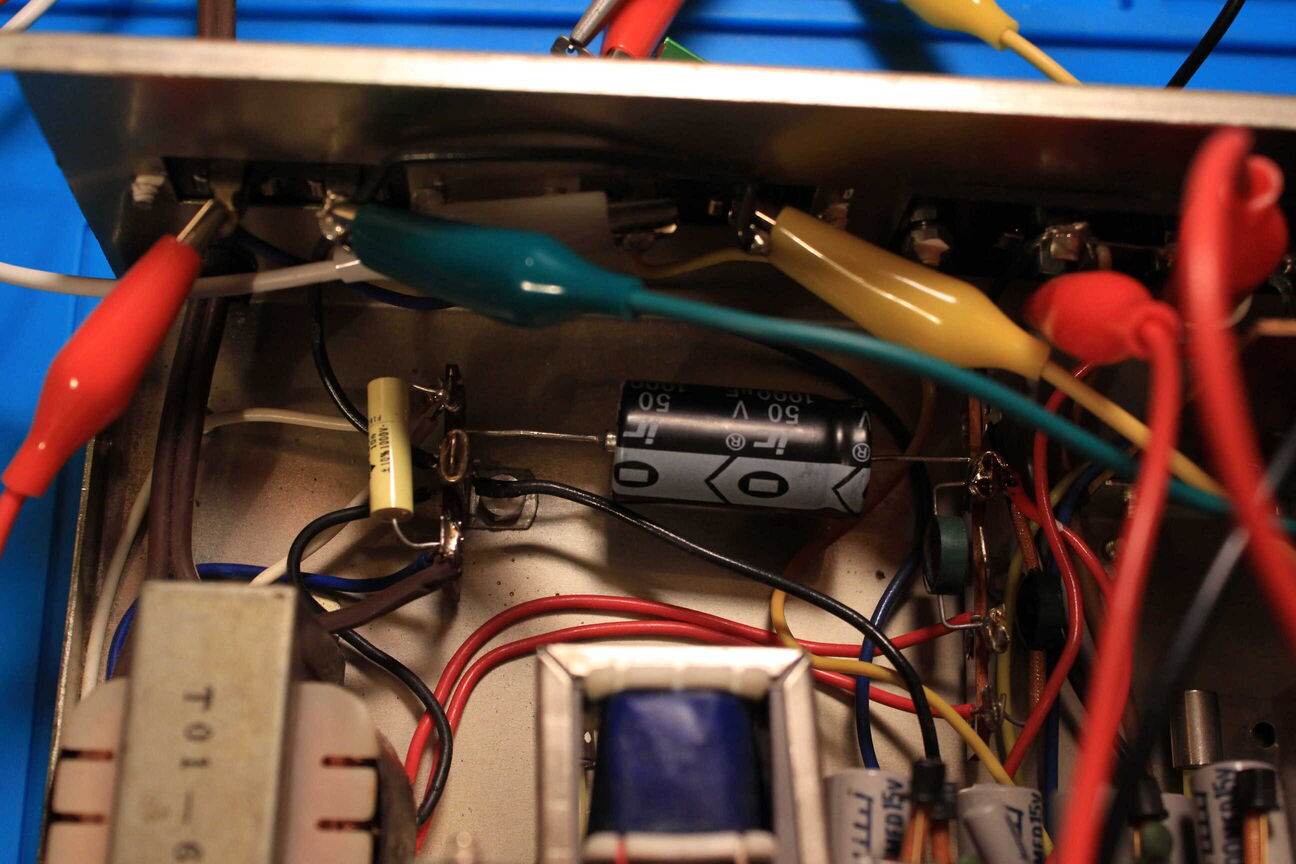
Here's a shot of the replacement caps soldered into the power supply section. The alligator clips are going to dummy load resistors for each channel so I can test the amp with a signal generator.
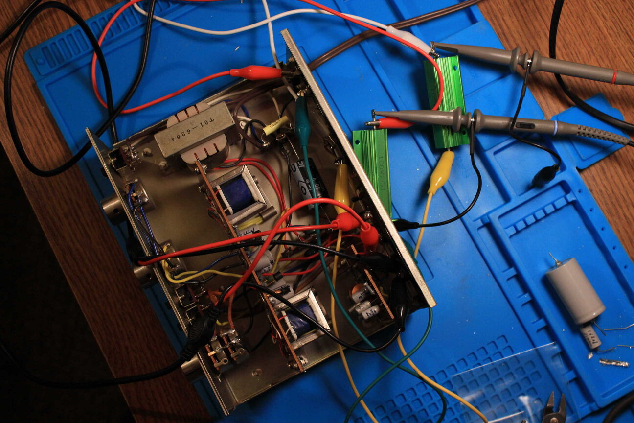
This is my setup for testing the amp. I was looking at both channels on an oscilloscope using a 1kHz tone. Both channels looked good through the aux and phono inputs and could be driven pretty hard before showing distortion.
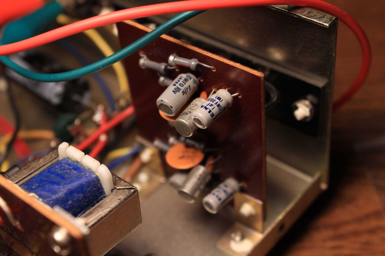
Since I already had replacements for them, I went ahead and replaced all of the electrolytic caps in the amplifier circuit. Heres a shot of the phono preamp before.
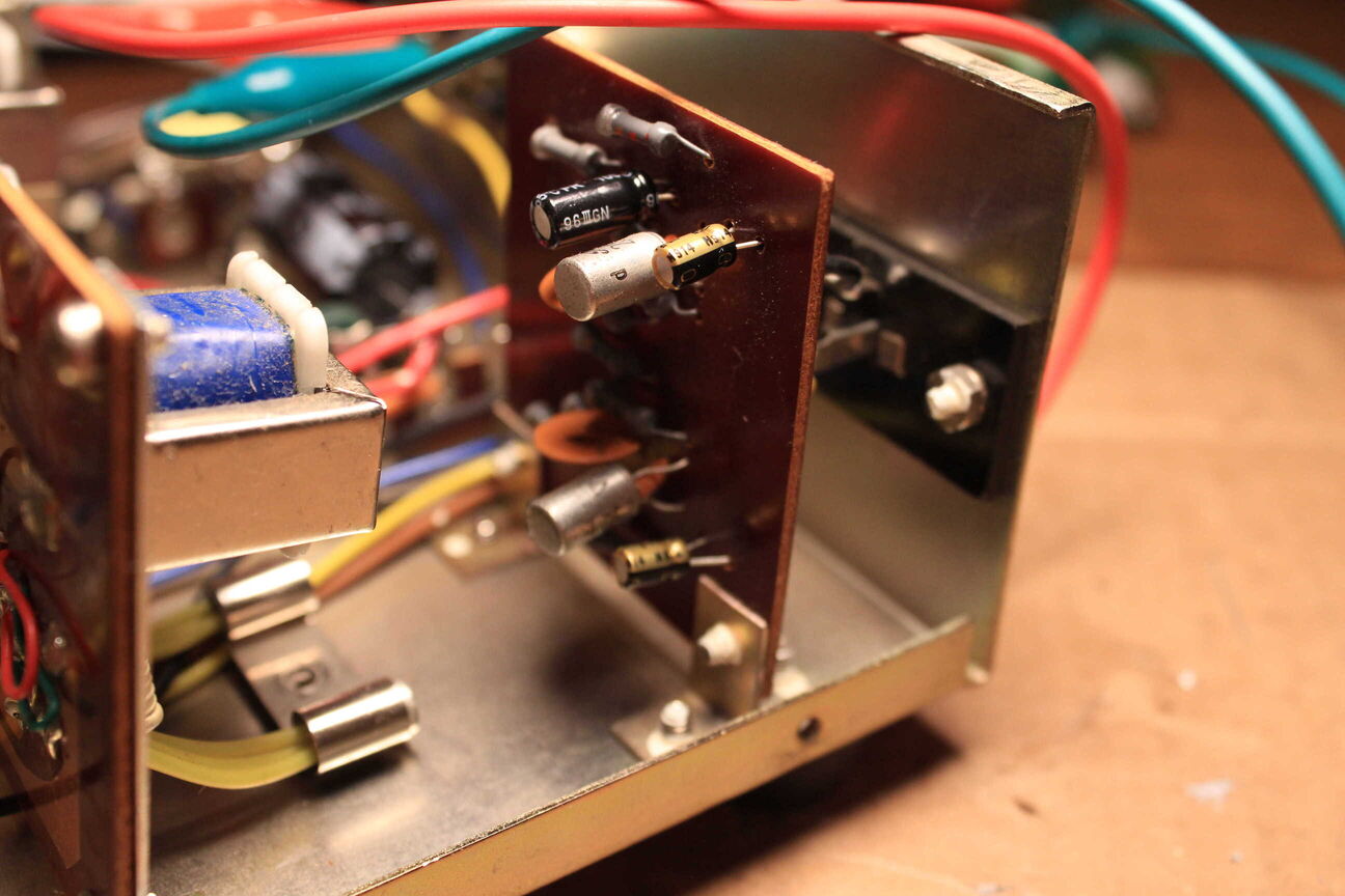
And here's the preamp after replacement. I used some Nichicon audio caps.
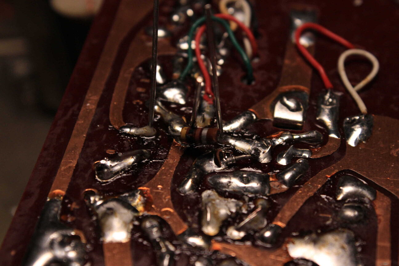
While resoldering a cap on the main amplifier board, I noticed a resistor that was soldered on the underside of the PCB that had split in half.
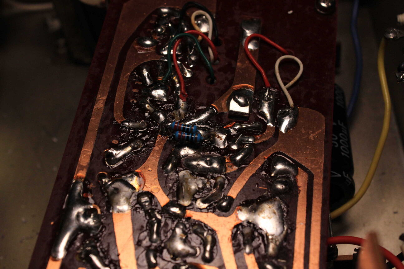
I used two 1/4 Watt resistors in parallel to be safe because I don't know what kind of current this resistor needs to carry but I doubt it would be over 1/2 a Watt.
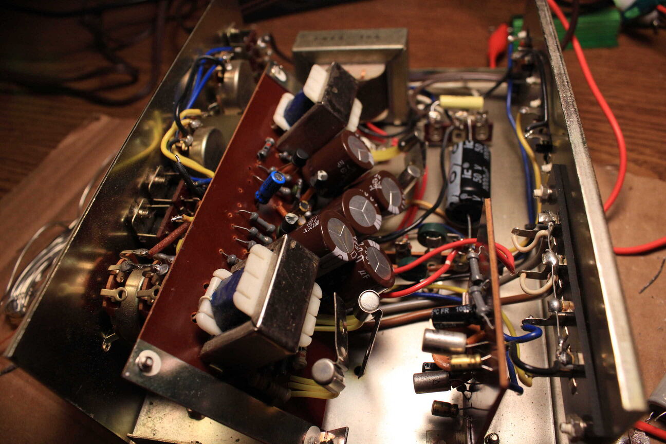
Here's a shot of the board after re-capping.
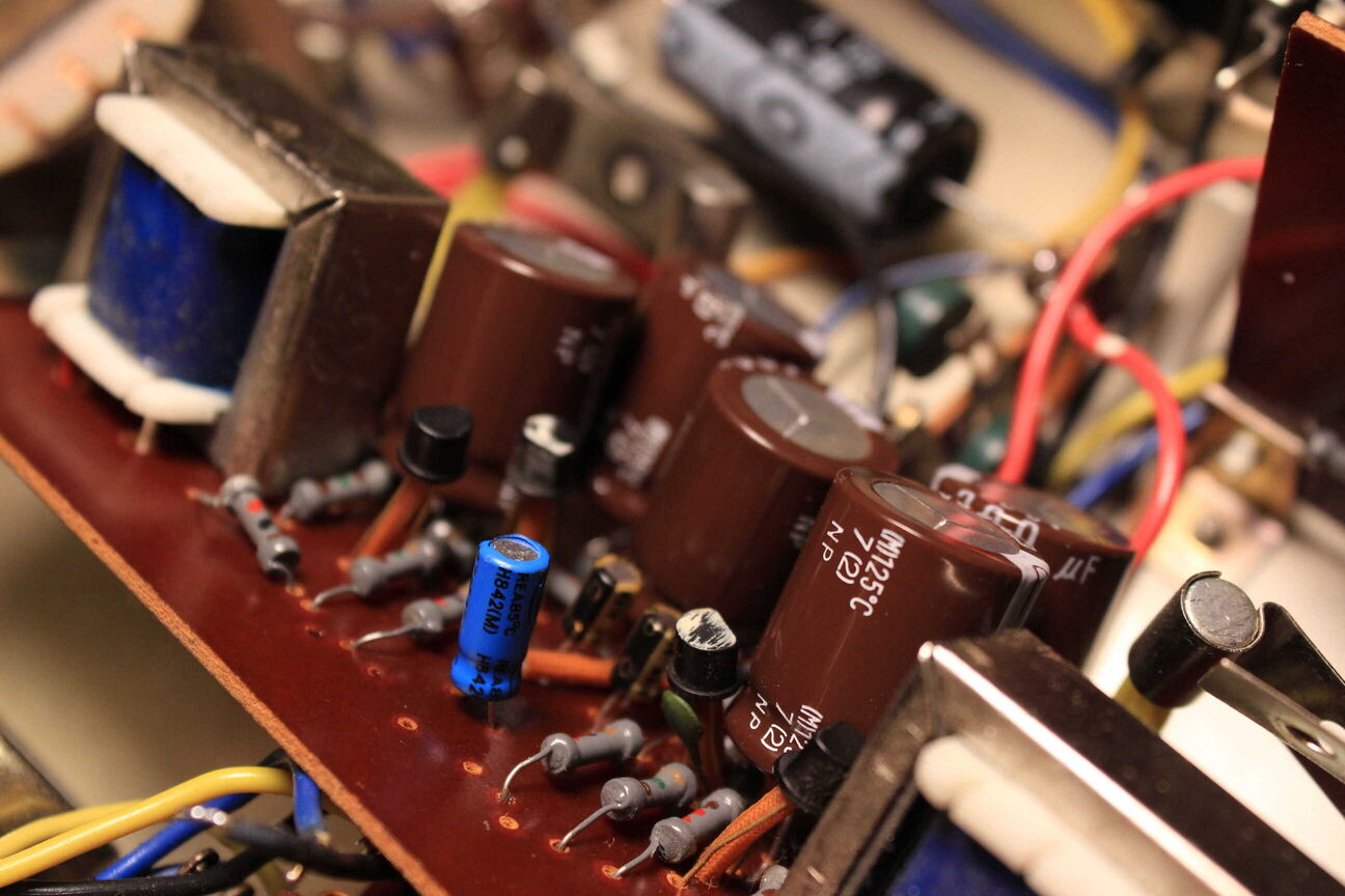
The board is a little more crowded now because I used capacitors with a higher voltage rating.
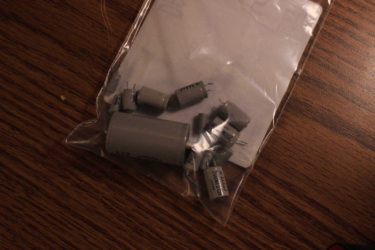
All the old caps
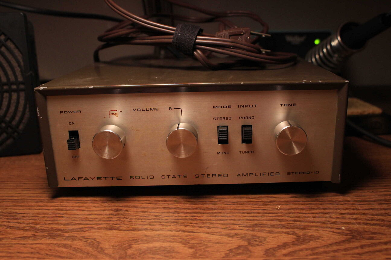
The last step was using contact cleaner on all of the pots and switches and then putting it all back together.
