
I first traced the entire circuit, comparing it with an original schematic. The blue components match the schematic and the yellow ones have been changed. I drew the tremolo circuit separately to make it easier. From here you can see the reverb circuit has some high frequency attenuating capacitors and the power section has cathode resistors added.

Here is the tremolo mod circuit. It looks like the oscillator is supposed to alter the bias through the cathode of the preamp tube.

Here are some shots of inside the chassis. The line cord had already been replaced. The death cap and auxilliary outlet were removed as well. I'm in favor of keeping the outlet because it's a perfect spot to plug in a pedal power supply.

The transformer matches the chassis

New screen and cathode resistors

I found a toasted resistor that I'm blaming on the tremolo mod.

A shot of the whole board

High-cut caps on the reverb tubes

This is how the tremolo pot was wired up. Those caps provide the cathode bypassing for the tremolo tubes. Very bizarre

The chassis was also full of holes

At least they missed the serial number

A bit high maybe?

The bright switches both tested open no matter the position so I cleaned the contacts directly.

Before

After

Caps removed from reverb section
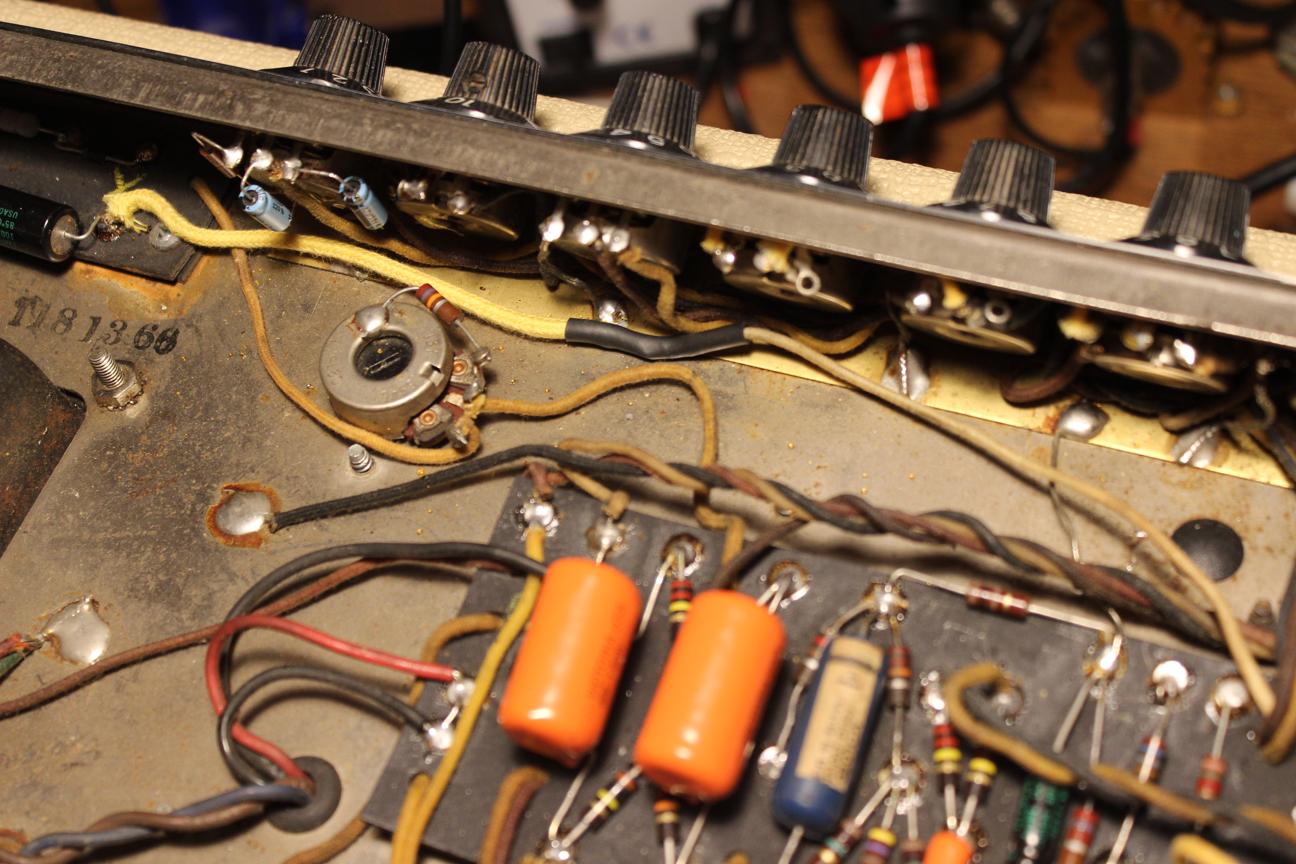
Running the original wire back to the bias supply. It had been cut and needed an extension.
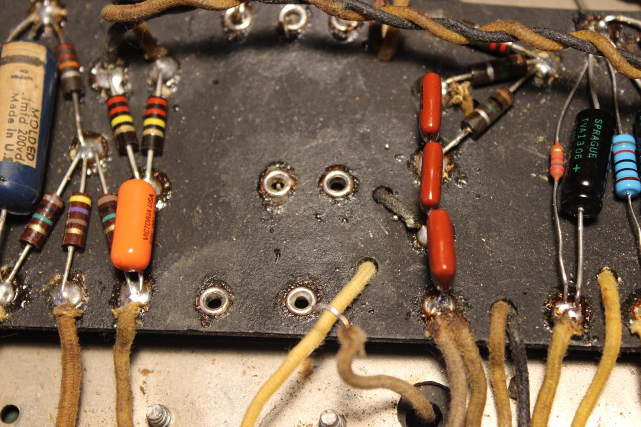
Removed all the wacky tremolo parts
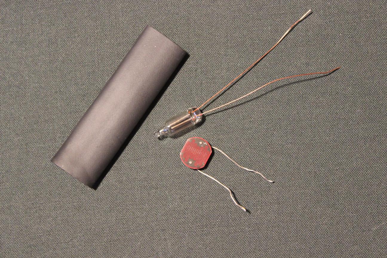
Assembled a new opto coupler
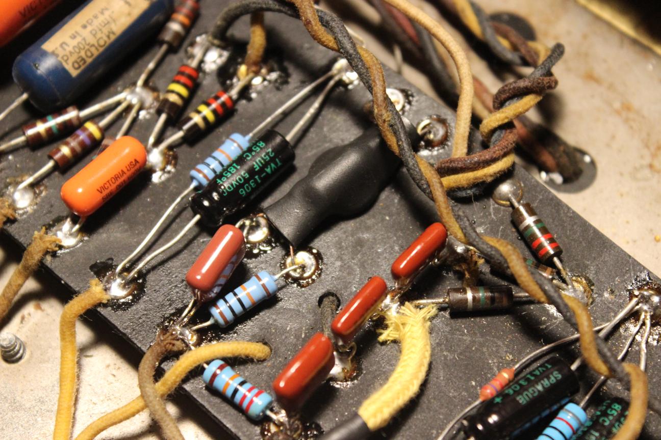
Back to normal
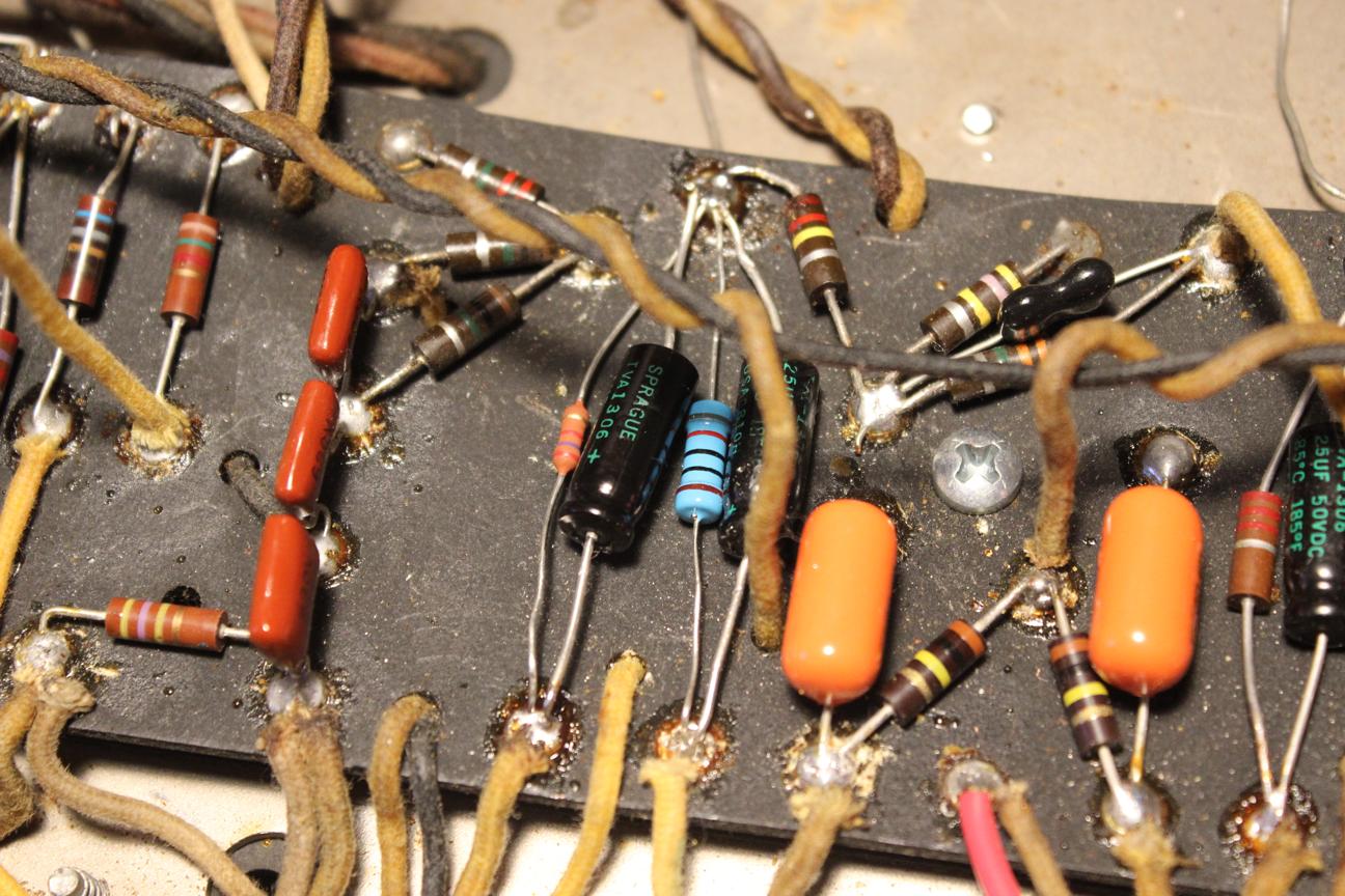
Bias on the preamp tubes back to normal too. At this point, I tested the new circuit and it sounded like it should.
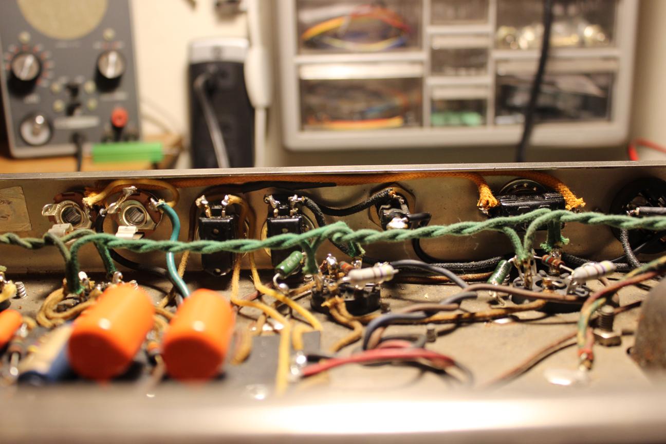
I also converted the ground switch to a feedback defeat switch. It's an easy, non-invasive mod that doubles tone options so why not?
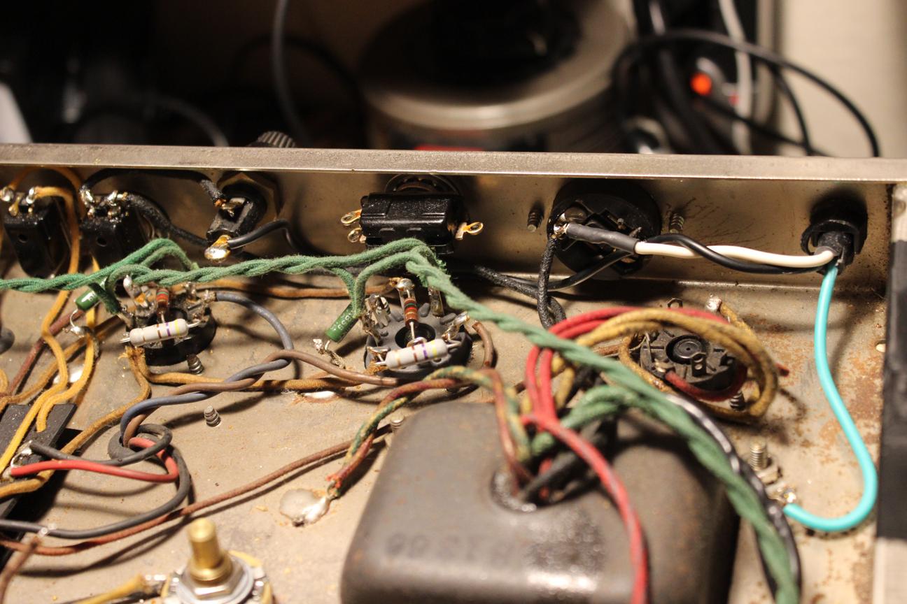
Aux. outlet restored
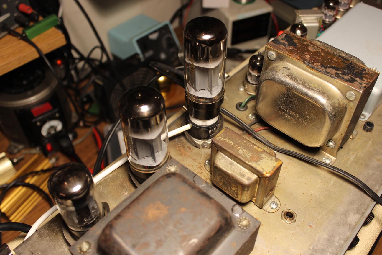
Setting the bias
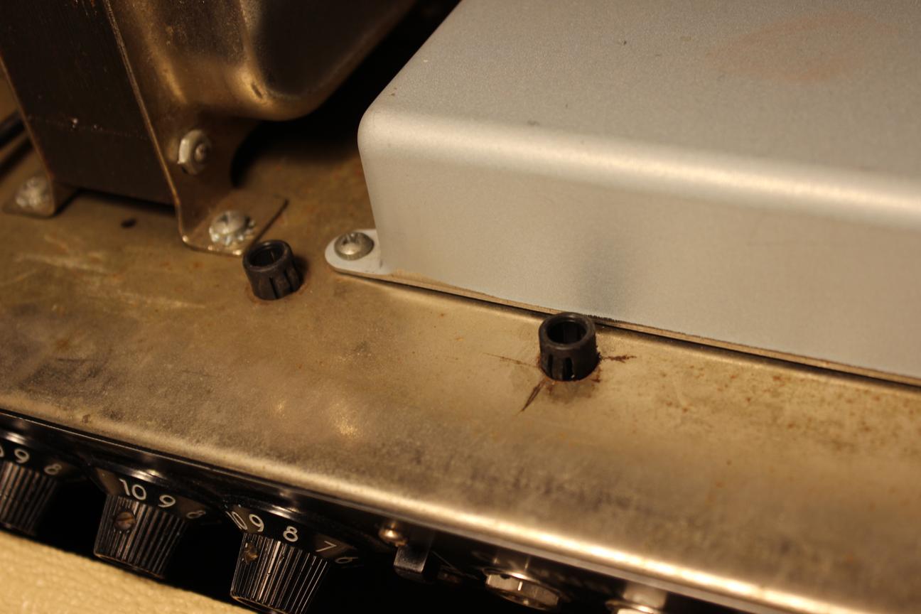
I noticed that there were hole covers installed on the wrong side
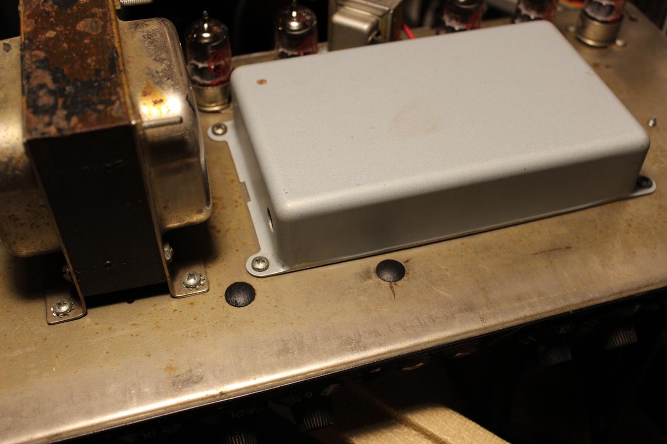
That just feels better
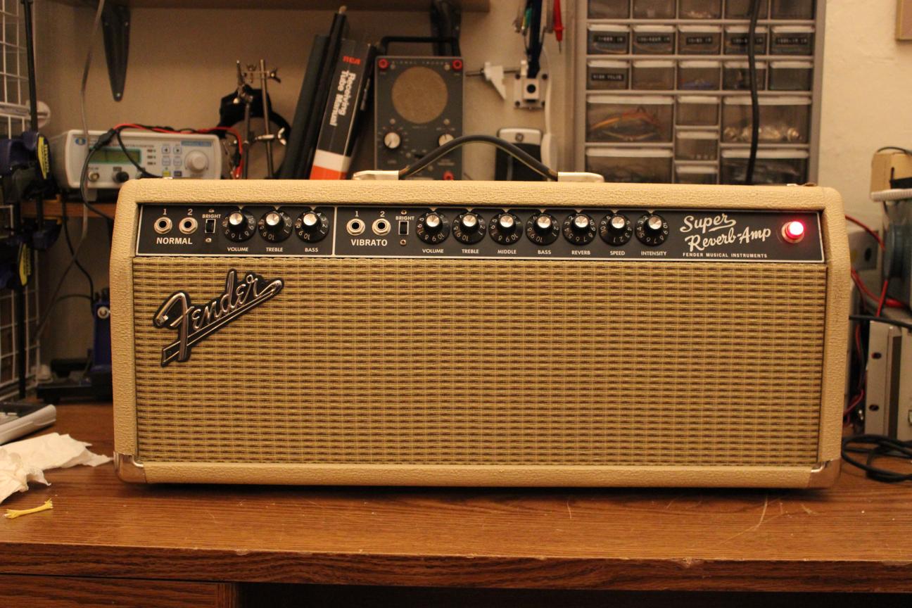
All done and sounding much better
 I first traced the entire circuit, comparing it with an original schematic. The blue components match the schematic and the yellow ones have been changed. I drew the tremolo circuit separately to make it easier. From here you can see the reverb circuit has some high frequency attenuating capacitors and the power section has cathode resistors added.
 Here is the tremolo mod circuit. It looks like the oscillator is supposed to alter the bias through the cathode of the preamp tube.
 Here are some shots of inside the chassis. The line cord had already been replaced. The death cap and auxilliary outlet were removed as well. I'm in favor of keeping the outlet because it's a perfect spot to plug in a pedal power supply.
 The transformer matches the chassis
 New screen and cathode resistors
 I found a toasted resistor that I'm blaming on the tremolo mod.
 A shot of the whole board
 High-cut caps on the reverb tubes
 This is how the tremolo pot was wired up. Those caps provide the cathode bypassing for the tremolo tubes. Very bizarre
 The chassis was also full of holes
 At least they missed the serial number
 A bit high maybe?
 The bright switches both tested open no matter the position so I cleaned the contacts directly.
 Before
 After
After
 Caps removed from reverb section
 Running the original wire back to the bias supply. It had been cut and needed an extension.
 Removed all the wacky tremolo parts
 Assembled a new opto coupler
 Back to normal
 Bias on the preamp tubes back to normal too. At this point, I tested the new circuit and it sounded like it should.
 I also converted the ground switch to a feedback defeat switch. It's an easy, non-invasive mod that doubles tone options so why not?
 Aux. outlet restored
 Setting the bias
 I noticed that there were hole covers installed on the wrong side
 That just feels better
 All done and sounding much better
